Electrical Symbols, Electrical Diagram Symbols

Electrical Symbols — Maintenance

Electrical Symbols — Switches and Relays

Electrical Drawing Software and Electrical Symbols

Basic Flowchart Symbols and Meaning


Process Flow Diagram Symbols

Samples of Flowchart

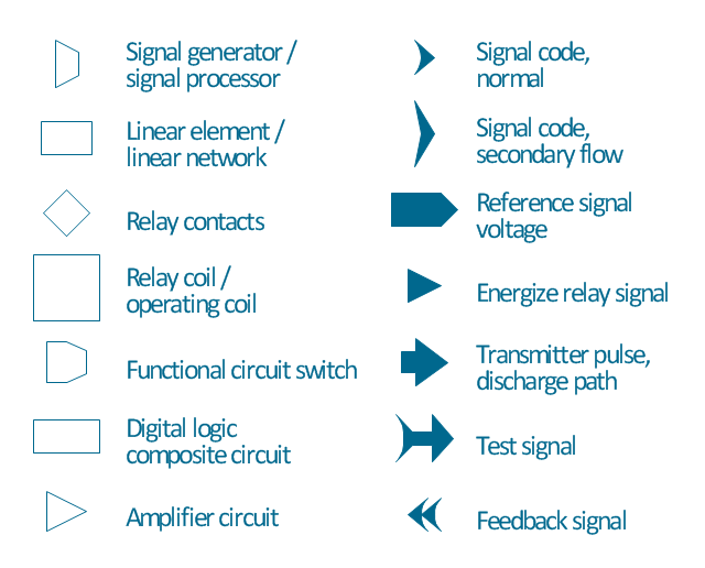
The vector stencils library "Maintenance" contains 14 symbols for maintaining electrical and electronic systems, including test, feedback and reference signals; pulses; relay contacts and coils; and composite and amplifier circuits.
Use these shapes for drawing electronic diagrams in the ConceptDraw PRO diagramming and vector drawing software extended with the Electrical Engineering solution from the Engineering area of ConceptDraw Solution Park.
www.conceptdraw.com/ solution-park/ engineering-electrical
Use these shapes for drawing electronic diagrams in the ConceptDraw PRO diagramming and vector drawing software extended with the Electrical Engineering solution from the Engineering area of ConceptDraw Solution Park.
www.conceptdraw.com/ solution-park/ engineering-electrical
Signal generator

Linear element

Relay contacts

Relay coil

Switch

Composite circuit

Amplifier

Signal code, normal

Signal code, secondary flow

Reference signal

Energize relay signal

Transmitter pulse

Test signal

Feedback

The vector stencils library "Maintenance" contains 14 symbols for maintaining electrical and electronic systems, including test, feedback and reference signals; pulses; relay contacts and coils; and composite and amplifier circuits.
The symbols example "Design elements - Maintenance" was drawn using the ConceptDraw PRO diagramming and vector drawing software extended with the Electrical Engineering solution from the Engineering area of ConceptDraw Solution Park.
The symbols example "Design elements - Maintenance" was drawn using the ConceptDraw PRO diagramming and vector drawing software extended with the Electrical Engineering solution from the Engineering area of ConceptDraw Solution Park.
Maintenance symbols
Local area network (LAN). Computer and Network Examples
 diagram")

- Matching Type Test About The Symbol Of Electricity
- Electrical Symbols — Switches and Relays | Control Schematic Pilot ...
- Create A Test Diagram For Online Electricity Bill Payment In
- Electrical Symbols , Electrical Diagram Symbols | IDEF3 Standard ...
- Failure Analysis Test Flow Chart For Electrical Components
- Download Electrical Trade Test Wiring Diagrams
- Create A Test Diagrams For Online Electricity Bill Payment
- Basic Flowchart Symbols and Meaning | Creat A Test Case Diagram ...
- Create Test Case Diagram For Online Electricity Bill Payment
- Electrical Symbols , Electrical Diagram Symbols | How To use House ...