Electrical Symbols, Electrical Diagram Symbols

Electrical Symbols — Logic Gate Diagram

How To use House Electrical Plan Software


Electrical Drawing Software and Electrical Symbols

Electrical Symbols — Electrical Circuits

Electrical Symbols — Switches and Relays

Electrical Diagram Software

Electrical Symbols — Power Sources

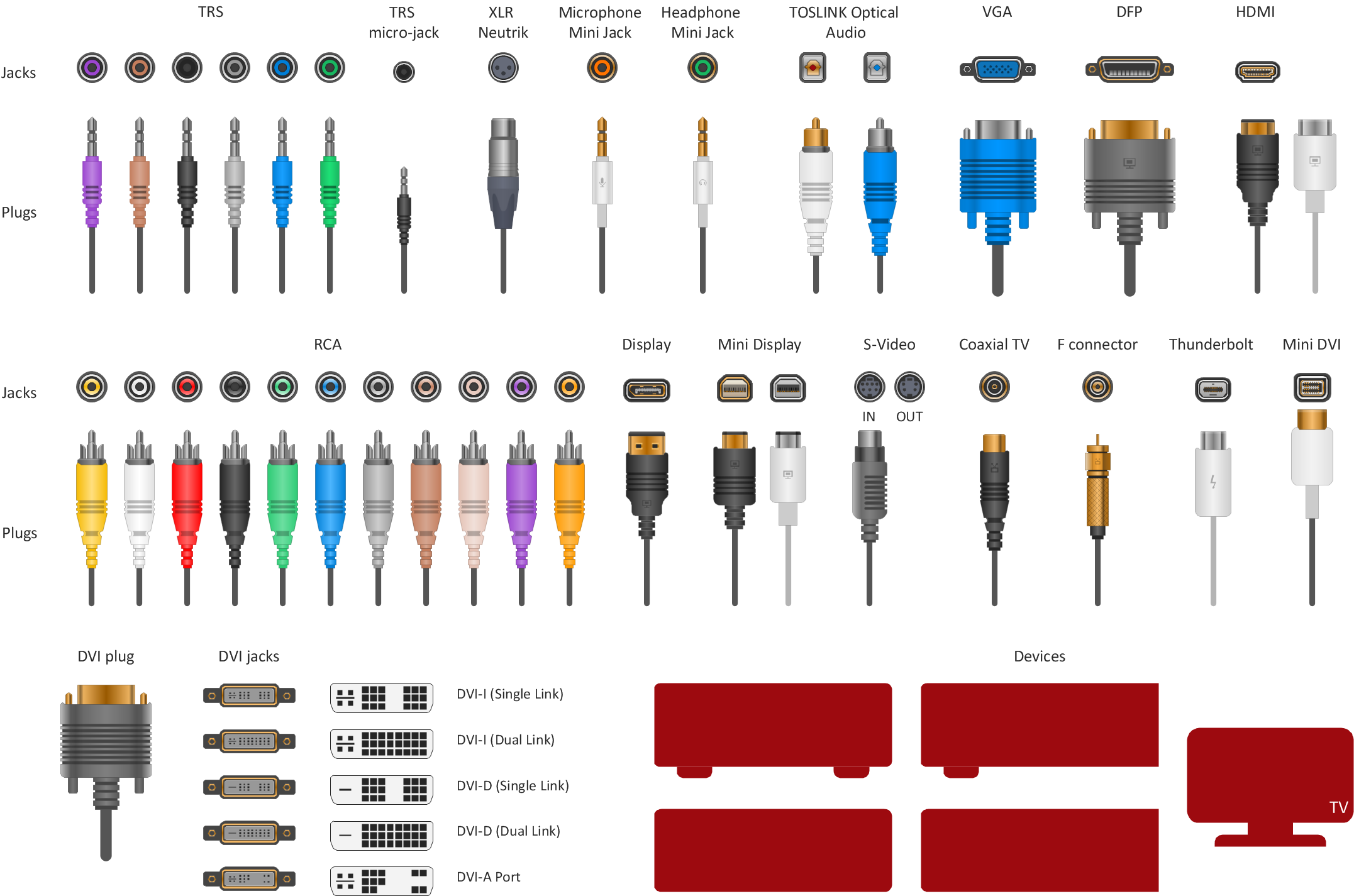
How To Print Audio & Video Connectors Schema in a Large Format
HelpDesk
How to Create an Electrical Diagram

- Electrical Print Format
- How to Create an Electrical Diagram Using ConceptDraw PRO ...
- How to Create an Electrical Diagram Using ConceptDraw PRO ...
- Engineering | How to Create an Electrical Diagram Using ...
- How To use House Electrical Plan Software | Blueprint Software ...
- House Wiring Blue Print
- Blue Print Of Electrical Diagram For Buldings
- How To Print Audio & Video Connectors Schema in a Large Format ...
- Kerala House Wiring Blue Print Digram
- Home Make Electrical Project Images And Blue Print