Electrical Symbols, Electrical Diagram Symbols

Electrical Symbols — Qualifying

Fault Tree Diagram

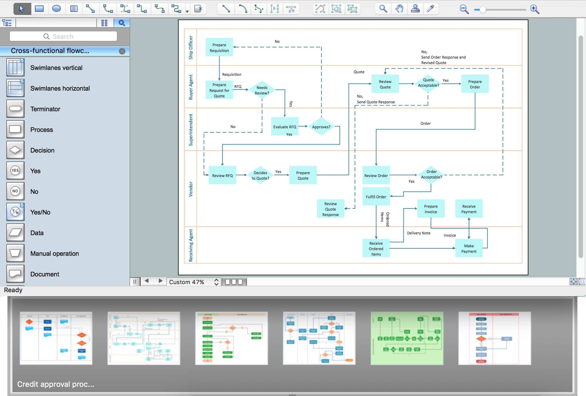
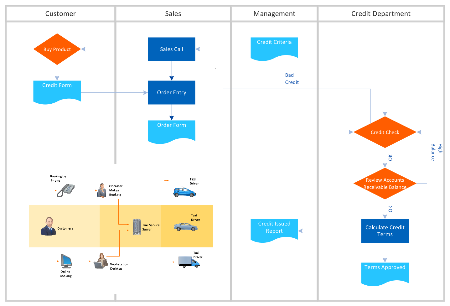
Process Flowchart

Local area network (LAN). Computer and Network Examples


 Electrical Engineering
This solution extends ConceptDraw DIAGRAM.9.5 (or later) with electrical engineering samples, electrical schematic symbols, electrical diagram symbols, templates and libraries of design elements, to help you design electrical schematics, digital and analog
Basic Flowchart Symbols and Meaning


 EXPRESS-G data Modeling Diagram
EXPRESS-G data Modeling Diagram solution extends the ConceptDraw DIAGRAM software functionality with capabilities of EXPRESS data modeling language, includes powerful data modeling tools, Express-G diagram tool, database diagram tool, database design tool, wide variety of pre-made vector objects of EXPRESS-G notation and EXPRESS-G diagrams samples allowing software developers, software designers, software engineers and other stakeholders to make their data models for information systems, to develop the databases, to learn the principles of construction EXPRESS-G diagrams and helping to draw their own EXPRESS-G Data Modeling Diagrams, Express-G Diagrams or Database Model Diagram without any efforts.
Flowchart Maker
 Specification and Description Language (SDL)
For people in the field of systems engineering or system design, working with specification and description language (sdl) and finite state machines (fsm).
- Electrical Fault Symbol
- Graphic Symbols For Electrical Electronic Components
- Cisco LAN fault -tolerance system - diagram | Graphic Technologies ...
- Fault Tree Analysis Software | Graphics Software for Business ...
- Electrical Symbols , Electrical Diagram Symbols | Design elements ...
- Amplifier - Circuit diagram | Electrical Symbols , Electrical Diagram ...
- Electrical Symbols — Electrical Circuits | Electrical Symbols ...
- Electrical Electronic Graphical Symbol Of Linear Ic
- Fault Tree Analysis Diagrams | Process Flowchart | Electrical ...
- Design elements - Fault tree analysis diagrams | How to Create a ...