The logic gate diagram example "2-bit ALU" was redesigned from the Wikimedia Commons file: 2-bit ALU.svg.
[commons.wikimedia.org/ wiki/ File:2-bit_ ALU.svg]
This file is licensed under the Creative Commons Attribution-Share Alike 3.0 Unported license. [creativecommons.org/ licenses/ by-sa/ 3.0/ deed.en]
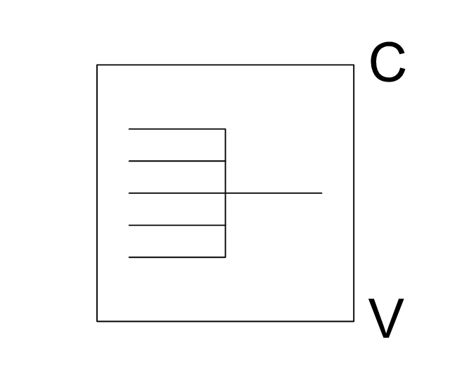
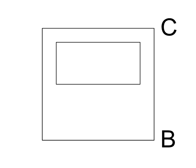
"In digital electronics, an arithmetic and logic unit (ALU) is a digital circuit that performs integer arithmetic and logical operations. The ALU is a fundamental building block of the central processing unit of a computer, and even the simplest microprocessors contain one for purposes such as maintaining timers. The processors found inside modern CPUs and graphics processing units (GPUs) accommodate very powerful and very complex ALUs; a single component may contain a number of ALUs. ...
Most of a processor's operations are performed by one or more ALUs. An ALU loads data from input registers. Then an external control unit tells the ALU what operation to perform on that data, and then the ALU stores its result into an output register. The control unit is responsible for moving the processed data between these registers, ALU and memory." [Arithmetic logic unit. Wikipedia]
The logic gate diagram example "2-bit ALU" was created using the ConceptDraw PRO diagramming and vector drawing software extended with the Electrical Engineering solution from the Engineering area of ConceptDraw Solution Park.
[commons.wikimedia.org/ wiki/ File:2-bit_ ALU.svg]
This file is licensed under the Creative Commons Attribution-Share Alike 3.0 Unported license. [creativecommons.org/ licenses/ by-sa/ 3.0/ deed.en]
"In digital electronics, an arithmetic and logic unit (ALU) is a digital circuit that performs integer arithmetic and logical operations. The ALU is a fundamental building block of the central processing unit of a computer, and even the simplest microprocessors contain one for purposes such as maintaining timers. The processors found inside modern CPUs and graphics processing units (GPUs) accommodate very powerful and very complex ALUs; a single component may contain a number of ALUs. ...
Most of a processor's operations are performed by one or more ALUs. An ALU loads data from input registers. Then an external control unit tells the ALU what operation to perform on that data, and then the ALU stores its result into an output register. The control unit is responsible for moving the processed data between these registers, ALU and memory." [Arithmetic logic unit. Wikipedia]
The logic gate diagram example "2-bit ALU" was created using the ConceptDraw PRO diagramming and vector drawing software extended with the Electrical Engineering solution from the Engineering area of ConceptDraw Solution Park.
Logic gate diagram

Local area network (LAN). Computer and Network Examples


The vector stencils library "Computer network" contains 51 symbols of computer network devices and equipment for drawing computer network diagrams.
"Network Mapping Software.
A number of software tools exist to design computer network diagrams / or generate visual maps of networks, servers, storage, services, data centers, and other peripherals. Broadly, there are two types of software tools - those that help create diagrams manually and those that generate them using automated / semi-automated approaches.
Type of Software.
(1) Manual - allows users to design and draw logical and physical topology diagrams by manually placing icons and connections.
(2) Automated - generate topology diagrams / maps by traversing the network and automatically discovering resident devices or by importing network data." [Comparison of network diagram software. Wikipedia]
ConceptDraw PRO is the software for manual design of computer network diagrams. The solutions of the Computer and Networks area in ConceptDraw Solution Park extend ConceptDraw PRO with vector stencils libraries, templates and examples for creating the computer network diagrams.
The symbols example "Computer network - Vector stencils library" was created using the ConceptDraw PRO diagramming and vector drawing software extended with the Computer and Networks solution from the Computer and Networks area of ConceptDraw Solution Park.
www.conceptdraw.com/ solution-park/ computer-and-networks
Laptop

Desktop computer

Firewall

Bus

Ethernet

Star network

FDDI Ring

Token-ring

Comm-link

Modem

Laser printer

Inkjet printer

Image scanner

City

Ethernet hub

Wireless router

Network switch

iPod Classic

iPhone/ iPod Touch

Xserve RAID

XServe

Apple Thunderbolt Display

Data store

Mac Pro

iMac

RAID

Mainframe

Rack-mountable server

Server

PDA

Cloud

Computer monitor

Workstation

Router

IP Phone

Fax

Mobile phone

Smartphone

Compact Disk

Mouse

Apple Wireless Mouse

Computer keyboard

Apple Keyboard

Radio tower

Satellite dish

Satellite

Webcam

AirPort Extreme

Airport Express

MacBook

iPhone 4

The vector stencils library "Initiation and annunciation" contains 9 vector shapes of Fire Alarm Control Panel (FACP) or Fire Alarm Control Unit (FACU) elements, triggering devices, audible alarm systems, timers, security control equipment, and recording devices.
Use it for drawing security and access plans of communications security systems, security schematics, and wiring diagrams with ConceptDraw PRO software extended with the Security and Access Plans solution from the Building Plans area of ConceptDraw Solution Park.
Use it for drawing security and access plans of communications security systems, security schematics, and wiring diagrams with ConceptDraw PRO software extended with the Security and Access Plans solution from the Building Plans area of ConceptDraw Solution Park.
Multiplex panel
Control panel
CPU

Keyboard

Printer
Audio device
Intercom
Two way radio
Document destroyer
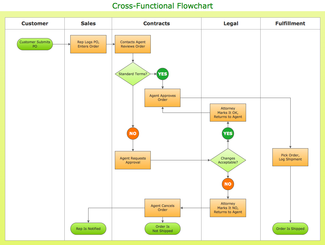
Business process Flow Chart — Event-Driven Process chain (EPC) diagrams

Technical Flow Chart

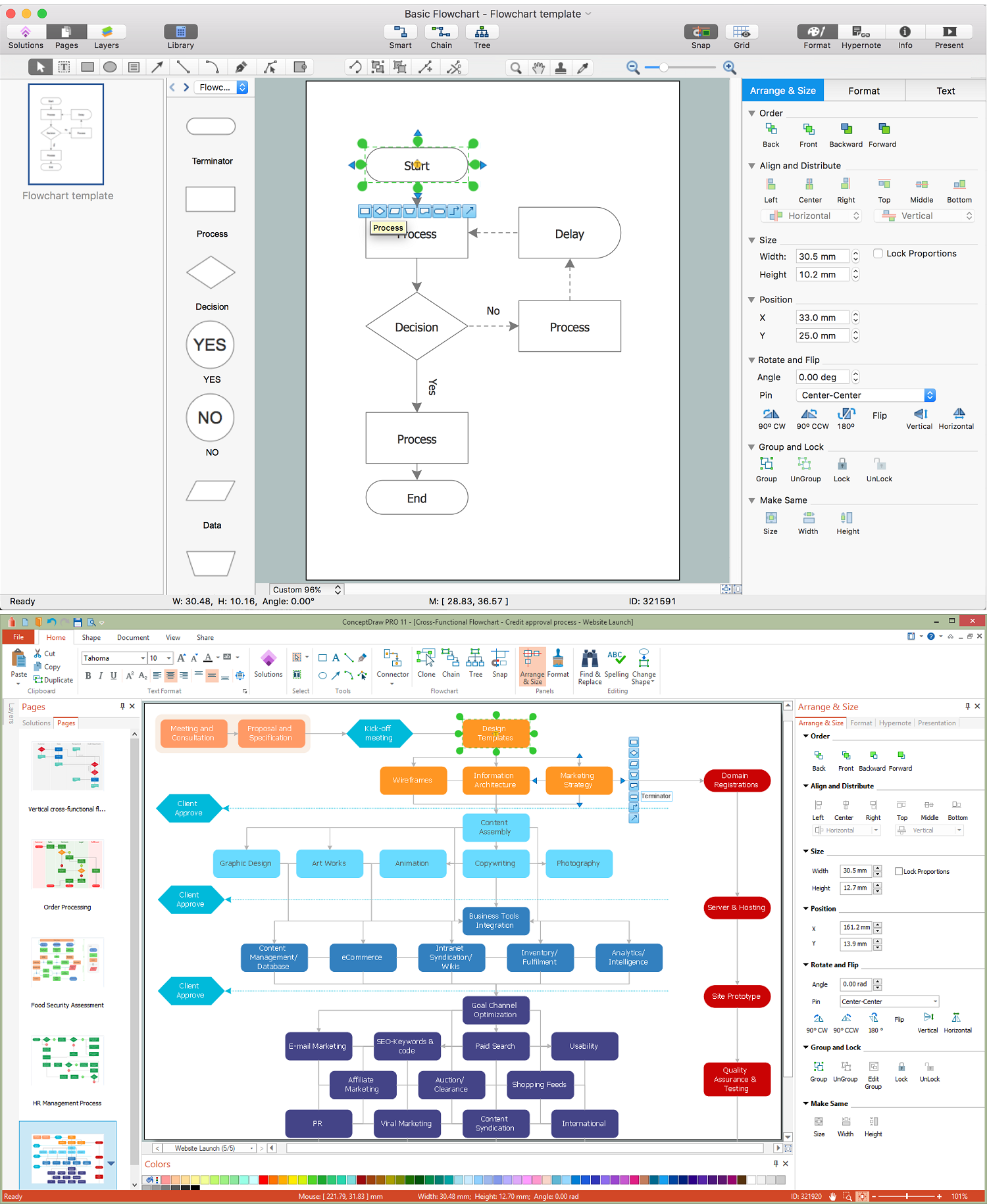
Basic Flowchart Examples
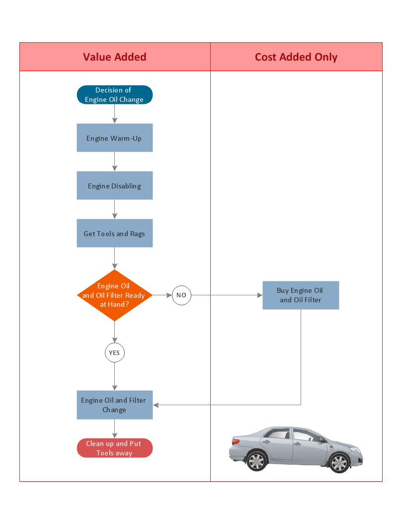
Process Modelling using Event-driven Process chain
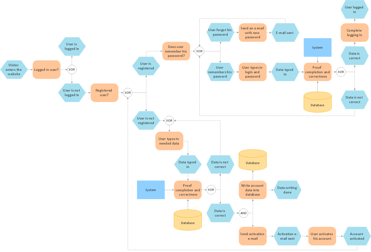
Cross Functional Flowchart Shapes
Creating a Simple Flowchart
- Central Processing Unit
- 2-bit ALU - Logic gate diagram | Electrical Engineering | Electrical ...
- Design elements - Logic gate diagram | Engineering | 2-bit ALU ...
- Diagram Of Arithmetic Logic Unit Using Logic Gates
- Drawing Symbol For Timers
- Process flow diagram - Typical oil refinery | Crude oil distillation unit ...
- 2-bit ALU - Logic gate diagram | How to Create a Fault Tree Analysis ...
- Timer Symbol Electrical Drawing
- Lcd Monitor Drawing
- Radio networks. Computer and Network Examples | Initiation and ...