Security Plans

How To Create CCTV Network Diagram

HelpDesk
How to Create a SysML Diagram Using ConceptDraw PRO
 diagram")
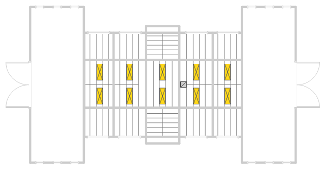
This reflected ceiling plan sample was created on the base of the RCP from the website of the University of Idaho.
"We tried a number of skylight layouts and decided to use a plan with five 2' by 6' skylights on each side of the gable roof at 18' above the floor. ... Reflected ceiling plan showing proposed skylights framed between roof rafters. The rafters are 2'9" apart only allowing for 2' wide skylights." [webpages.uidaho.edu/ arch571/ AASouth4.htm]
The skylights layout example "Studio space RCP" was created using the ConceptDraw PRO diagramming and vector drawing software extended with the Reflected Ceiling Plans solution from the Building Plans area of ConceptDraw Solution Park.
Reflected ceiling plan
ERD Symbols and Meanings


Column Chart Software

Architecture Diagrams

Cross-Functional Flowchart


- Sliding Door On A Floor Plan
- Network layout floorplan - Vector stencils library | Home floor plan ...
- Reflected Ceiling Plans | How to Create a Reflected Ceiling Floor ...
- Home floor plan template | Security system plan | Air handler- HVAC ...
- Mini Hotel Floor Plan . Floor Plan Examples
- Warehouse layout floor plan | Warehouse with conveyor system ...
- Warehouse layout floor plan | Warehouse with conveyor system ...
- HVAC Plans | Block diagram - Automotive HVAC system | Design ...
- Warehouse with conveyor system - Floor plan | Warehouse with ...
- Plant Layout Plans | Store Layout Software | Warehouse with ...
- Cabinet Design Software | Network Diagramming Software for ...
- Flow chart Example. Warehouse Flowchart | Warehouse layout floor ...
- Security system plan | Room planning with ConceptDraw PRO | How ...
- Ethernet local area network layout floor plan | Local network ...
- Floor Plan Socket Symbol
- Create Floor Plans Easily With ConceptDraw PRO | Power socket ...
- Cabinet Design Software | Interior Design Software. Building Plan ...
- Plant Layout Plans | Warehouse layout floor plan | Flow chart ...
- How To use House Electrical Plan Software | Create Floor Plans ...
- Network Layout Floor Plans | Design elements - Network layout ...