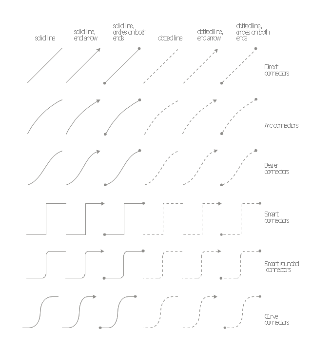
The vector stencils library "Management connectors" contains 36 connector shapes: solid and dotted lines with or without arrows or circles on the ends.
Use it to illustrate your management infograms with block diagrams.
"Block diagram is a diagram of a system in which the principal parts or functions are represented by blocks connected by lines that show the relationships of the blocks." [Block diagram. Wikipedia]
The shapes example "Design elements - Management connectors" was created using the ConceptDraw PRO diagramming and vector drawing software extended with the Management Infographics solition from the area "Business Infographics" in ConceptDraw Solution Park.
Connectors
Garrett IA Diagrams with ConceptDraw PRO

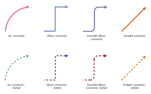
The vector stencils library "Workflow connectors" contains 8 flow lines.
Use it to design your business process workflow diagrams with ConceptDraw PRO software.
"A flowchart is a type of diagram that represents an algorithm, workflow or process, showing the steps as boxes of various kinds, and their order by connecting them with arrows. ...
Flow Line ... An arrow coming from one symbol and ending at another symbol represents that control passes to the symbol the arrow points to. The line for the arrow can be solid or dashed. The meaning of the arrow with dashed line may differ from one flowchart to another and can be defined in the legend." [Flowchart. Wikipedia]
The flowchart arrows example "Design elements - Workflow connectors" is included in the Business Process Workflow Diagrams solution from the Business Processes area of ConceptDraw Solution Park.
Flow lines
HelpDesk
How to Connect Objects in ConceptDraw PRO on PC


 Business Processes Area
Solutions of Business Processes area extend ConceptDraw PRO software with samples, templates and vector stencils libraries for drawing business process diagrams and flowcharts for business process management.
Use Case Diagrams technology with ConceptDraw PRO

 Business Process Diagrams
Business Process Diagrams solution extends the ConceptDraw PRO BPM software with RapidDraw interface, templates, samples and numerous libraries based on the BPMN 1.2 and BPMN 2.0 standards, which give you the possibility to visualize equally easy simple and complex processes, to design business models, to quickly develop and document in details any business processes on the stages of project’s planning and implementation.
The vector stencils library "UML composite structure diagrams" contains 36 symbols for the ConceptDraw PRO diagramming and vector drawing software.
"The key composite structure entities identified in the UML 2.0 specification are structured classifiers, parts, ports, connectors, and collaborations.
(1) Part : A part represents a role played at runtime by one instance of a classifier or by a collection of instances. The part may only name the role, it may name an abstract superclass, or it may name a specific concrete class. The part can include a multiplicity factor, such as the [0..*] shown for Viewer in the diagram.
(2) Port : A port is an interaction point that can be used to connect structured classifiers with their parts and with the environment. Ports can optionally specify the services they provide and the services they require from other parts of the system. In the diagram, each of the small squares is a port. Each port has a type and is labelled with a name, such as "var", "indVar1", or "view" in the diagram. Ports may contain a multiplicity factor, for example.
Ports can either delegate received requests to internal parts, or they can deliver these directly to the behavior of the structured classifier that the port is contained within. Public ports that are visible in the environment are shown straddling the boundary, while protected ports that are not visible in the environment are shown inside the boundary. All the ports in the diagram are public, except for the view port along the right boundary of FibonacciSystem.
(3) Connector : A connector binds two or more entities together, allowing them to interact at runtime. The connector is shown as a line between some combination of parts, ports and structured classifiers. The diagram shows three connectors between ports, and one connector between a structured classifier and a part.
(4) Collaboration : A collaboration is generally more abstract than a structured classifier. It is shown as a dotted oval containing roles that instances can play in the collaboration.
(5) Structured classifier : A StructuredClassifier represents a class, often an abstract class, whose behavior can be completely or partially described through interactions between parts." [Composite structure diagram. Wikipedia]
The example "Design elements - UML composite structure diagrams" is included in the Rapid UML solution from the Software Development area of ConceptDraw Solution Park.
UML composite structure diagram symbols

- Dotted Line In Flowchart Meaning
- Flowchart Dotted Line
- Org Chart Generator Dotted Lines
- Vector stencils library - IDEF0 | How to Set Line Jumps for Smart ...
- What Does Dotted Line Mean In Flow Chart
- How to Set Line Jumps for Smart Connectors in ConceptDraw PRO ...
- Flow Chart Broken Line Meaning
- Conceptdraw Connection Line With Object
- Dotted Line Process Map
- Meaning Of Dotted Line In Er Diagram
- What Does Dotted Line Shows In Flow Chart
- Organizational Chart Broken Line Symbol
- Why We Use Dotted Line Ina Flow Chart
- Entity Relationship Diagram Symbols | ERD Symbols and Meanings ...
- Dotted Arrow In Conceptdraw Pro
- Curved Line Design Png
- How to Set Line Jumps for Smart Connectors in ConceptDraw PRO ...
- Flowchart Dotted Lines
- Broken Lines In Organizational Chart
- Arched Line Vector