Entity-Relationship Diagram (ERD) with ConceptDraw PRO


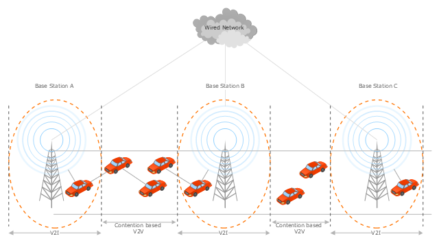
This vehicular network diagram sample was drawn on the base of the picture "Inter-Vehicle Communication (IVC) systems" from the website of the Department of Electrical and Computer Engineering, the Ohio State University.
[www2.ece.ohio-state.edu/ ~ekici/ res_ ivc.html]
"Driver assistance systems are meant to support drivers with driving process in order to avoid traffic accidents, speed up the traffic and have a higher control over the traffic in general. There are a lot of systems which give support to the drivers, such as adaptive cruise control, traffic sign recognition, automatic parking, etc. ... the vehicular communication systems ... use the capacity of the vehicles to communicate, not only between them but also with infrastructures. All the information is collected and processed to offer use
ful services. Wireless Sensor Networks (WSN) are widely used in this area. With the incoming upgrades of these networks, they are becoming an attractive solution to give support with the communication mechanisms between vehicles." [mi.fu-berlin.de/ inf/ groups/ ag-tech/ teaching/ 2011_ SS/ S_ 19510b_ Proseminar_ Technische_ Informatik/ daniel-lopez-report.pdf?1346662267]
The vehicular network diagram example "Inter-vehicle communication systems" was created using the ConceptDraw PRO diagramming and vector drawing software extended with the Vehicular Networking solution from the Computer and Networks area of ConceptDraw Solution Park.
Vehicular network diagram
Event-Driven Process Chain Diagram Software

Process Flowchart


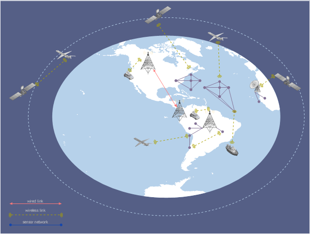
This global vehicular network diagram sample represents the independent regional telematics network.
"Telematics typically is any integrated use of telecommunications and informatics, also known as ICT (Information and Communications Technology). Hence the application of telematics is with any of the following:
(1) The technology of sending, receiving and storing information via telecommunication devices in conjunction with affecting control on remote objects.
(2) The integrated use of telecommunications and informatics, for application in vehicles and with control of vehicles on the move.
(3) Telematics includes but is not limited to Global Positioning System technology integrated with computers and mobile communications technology in automotive navigation systems. ...
Practical applications of vehicle telematics:
1. Vehicle tracking is a way of monitoring the location, movements, status and behaviour of a vehicle or fleet of vehicles. ...
2. Trailer tracking is the technology of tracking the movements and position of an articulated vehicle's trailer unit...
3. Container tracking. Freight containers can be tracked by GPS...
4. Cold store freight trailers ... used to deliver fresh or frozen foods are ... incorporating telematics to gather time-series data on the temperature inside the cargo container...
5. Fleet management includes the management of ships and or motor vehicles such as cars, vans and trucks. Fleet ... Management can include ... vehicle telematics (tracking and diagnostics)...
6. Satellite navigation in the context of vehicle telematics is the technology of using a GPS and electronic mapping tool to enable the driver of a vehicle to locate a position, plan a route and navigate a journey.
7. Mobile data is the use of wireless data communications using radio waves to send and receive real time computer data to, from and between devices used by field based personnel. ...
8. Wireless vehicle safety communications telematics aid in car safety and road safety. ...
9. Emergency warning system for vehicles. Telematics ... are self-orientating open network architecture structures of variable programmable intelligent beacons ... to accord ... warning information with surrounding vehicles in the vicinity of travel, intra-vehicle, and infrastructure. ...
10. Intelligent vehicle technologies. Telematics comprise electronic ... devices ... to provide precision repeatability functions ... emergency warning validation performance reconstruction. ...
11. Car clubs. Telematics-enabled computers allow organizers to track members' usage and bill them on a pay-as-you-drive basis. ...
12. Auto insurance. The basic idea of telematic auto insurance is that a driver's behavior is monitored directly while the person drives and this information is transmitted to an insurance company." [Telematics. Wikipedia]
The example "Independent regional networks diagram" was created using the ConceptDraw PRO diagramming and vector drawing software extended with the Vehicular Networking solution from the Computer and Networks area of ConceptDraw Solution Park.
Global vehicular network diagram
Road Transport - Design Elements

Electrical Symbols — Terminals and Connectors

UML Diagram of Parking

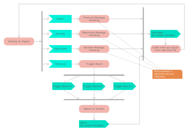
"Alarm triggers.
The individual triggers for a car alarm vary widely, depending on the make and model of the vehicle, and the brand and model of the alarm itself (for aftermarket alarms). Since aftermarket alarms are designed to be universal (i.e., compatible with all 12 volt negative ground electrical systems as opposed to one carmaker's vehicles), these commonly have trigger inputs that the installer/ vehicle owner chooses not to connect, which additionally determines what will set the alarm off." [Car alarm. Wikipedia]
The UML activity diagram example " Alarm trigger processing" was created using the ConceptDraw PRO diagramming and vector drawing software extended with the Rapid UML solution from the Software Development area of ConceptDraw Solution Park.
UML activity diagram
Using Fishbone Diagrams for Problem Solving

- Block Diagram Of Car Structure In Automobile Engineering
- Automated Car Parking System Use Case Diagram
- Sequence Diagram For Car Parking System
- Create Block Diagram | Car Structure Diagram
- Car Engine Basic Diagram And Block Diagram
- Car Rental Booking Dfd Diagram
- Enhance Entity Relation Diagram Of A Car Showroom
- Class Diagram For Car Parking System
- Er Diagram For Car Rental
- Entity-Relationship Diagram (ERD) | Auto Loan Process Er Diagram