Metropolitan area networks (MAN). Computer and Network Examples
. Computer and Network Examples")

How to Create Cisco Network Diagram
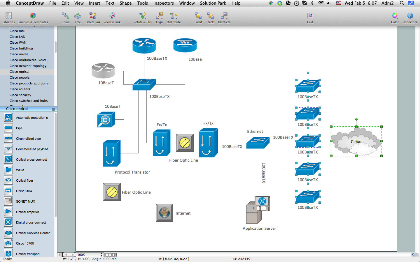
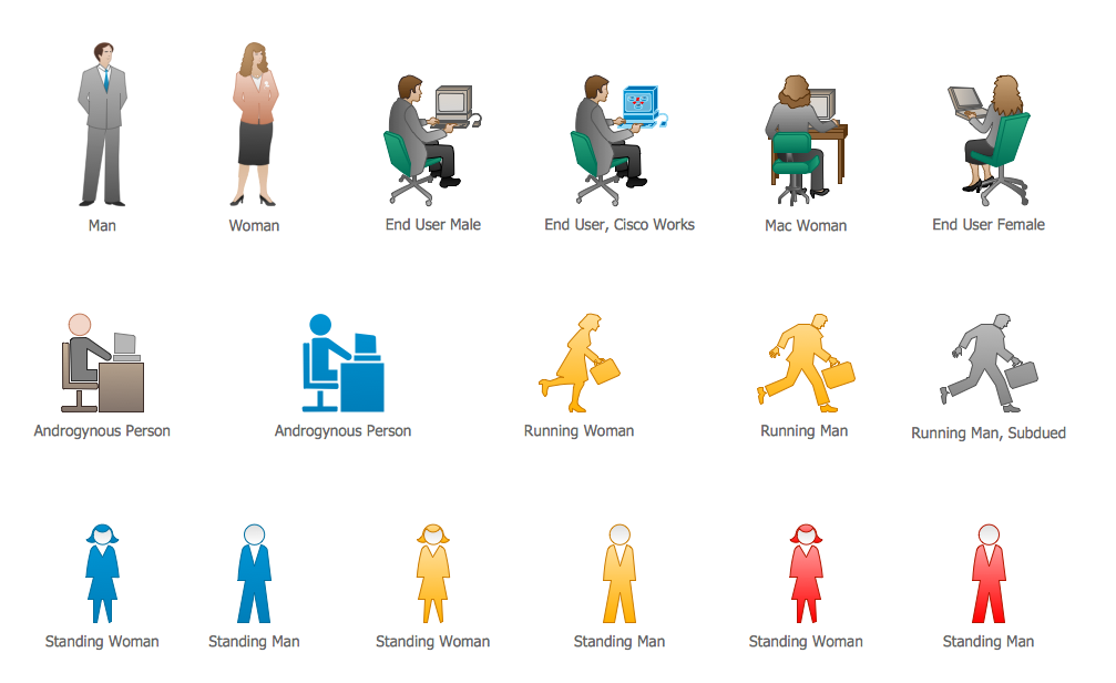
Cisco People. Cisco icons, shapes, stencils and symbols
Local area network (LAN). Computer and Network Examples
 diagram")
"Man-to-man defense is a type of defensive tactic used in team sports such as American football, association football, basketball, and netball, in which each player is assigned to defend and follow the movements of a single player on offense. Often, a player guards his counterpart (e.g. center guarding center), but a player may be assigned to guard a different position. The strategy is not rigid however, and a player might switch assignment if needed, or leave his own assignment for a moment to double team an offensive player. The term is commonly used even in women's basketball, though the gender-neutral 'player-to-player' also has some usage. ...
When defending the ball (i.e. guarding the man with the basketball) away from the basket in basketball, players typically should use a version of the following technique: The defender stands and faces the opponent. He is positioned between the ball and the basket and may be angled in one direction or another depending on the defensive scheme of that defender's team. He has his feet positioned beyond shoulder width with most of the weight distributed to the balls of his feet. However, the defender's heels should not be off the floor as this will put him off balance. The defender's knees should be bent at roughly a ninety degree angle with the bottom of his thighs parallel to the ground. This will place the defenders buttocks in a seated position. The defenders back should be straight with just a slight tilt forward. This will place the defender's head over the center of his body and maintain proper balance. Depending on the teachings of his coach, the defender should position his hands wide as if he were stretching his wingspan or place one hand high and one hand low." [Man-to-man defense. Wikipedia]
The basketball positions diagram example "Man-to-man basketball defense drill" was created using the ConceptDraw PRO diagramming and vector drawing software extended with the Basketball solution from the Sport area of ConceptDraw Solution Park.
www.conceptdraw.com/ solution-park/ sport-basketball
Basketball positions diagram

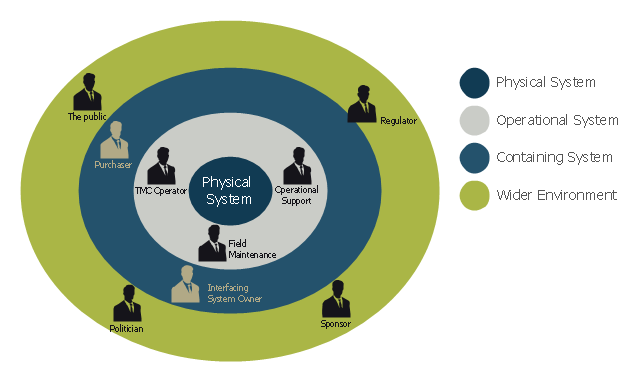
This onion diagram example was designed on the base of figure "Stakeholders for a System" in the slide presentation "A103: Introduction to ITS Standards Requirements Development" from the U.S. Department of Transportation (US DOT) website.
"“Stakeholders for a System.” A graphic of four concentric circles arranged like an archery target. The innermost circle is a reddish tan. The three bands of colors that are further from the center are in lighter shades of tan. This is called an “onion diagram” as onions are made up of multiple layers. The inner circle is labeled “Physical System.” The next layer outward is labeled “Operational System.” The next layer outward is labeled “Containing System.” The outermost layer is labeled “Wider Environment.” There are smaller black graphics of person positioned in the different layers of the diagram. Each person has a project role next to it as follows: 1) Inner Circle has no people – It represents the system; 2) Next Layer Outward has three people labeled TMC Operator, Field Maintenance, and Operational Support respectively; 3) Next Layer Outward has two people labeled Interfacing System Owner and Purchaser respectively; and 4) Outermost Layer has four people labeled Sponsor of the Project, Regulatory Agency, Public, and Politician respectively. The picture demonstrates while they are all stakeholders, different stakeholders have different levels of influence on the physical system to be defined. The most influence coming from those closest to the center."
[pcb.its.dot.gov/ standardstraining/ mod04/ ppt/ m04ppt.htm]
The onion diagram example "System stakeholders diagram" was drawn using the ConceptDraw PRO software extended with the Stakeholder Onion Diagrams solution from the Management area of ConceptDraw Solution Park.
Onion diagram example
Campus Area Networks (CAN). Computer and Network Examples

UML Diagram Types List

Network Topologies


Electrical Symbols — Terminals and Connectors

- Diagrams Of Lan Wan Man Networks
- Wireless Networks | Block Diagram For Lan Wan Man Pan
- Fish Bone Diagram For Man Machine Material And Method
- Manufacturing 8 Ms fishbone diagram - Template | 8m Method ...
- What Is Man Type Flow Process Chart
- Manufacturing 8 Ms fishbone diagram - Template | Fishbone ...
- Explain Lan Man Wan With Diagrams
- Network organization chart | Model Based On Lan Man Wan
- Computer Network Diagrams | Lan Man Wan Simple Block Diagram
- Network Diagrams for Bandwidth Management | Man Type Flow ...