Network Gateway Router


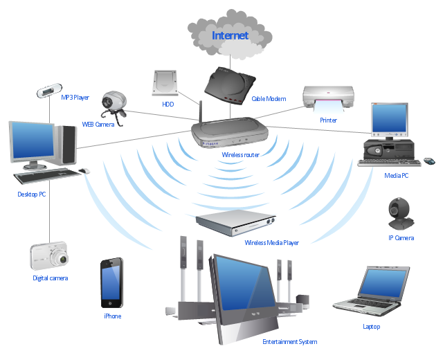
"A wireless network is any type of computer network that uses wireless data connections for connecting network nodes. Wireless networking is a method by which homes, telecommunications networks and enterprise (business) installations avoid the costly process of introducing cables into a building, or as a connection between various equipment locations. Wireless telecommunications networks are generally implemented and administered using radio communication. This implementation takes place at the physical level (layer) of the OSI model network structure. Examples of wireless networks include cell phone networks, Wi-Fi local networks and terrestrial microwave networks." [Wireless network. Wikipedia]
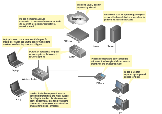
This wireless router network diagram example was created using the ConceptDraw PRO diagramming and vector drawing software extended with the Computer and Networks solution from the Computer and Networks area of ConceptDraw Solution Park.
This wireless router network diagram example was created using the ConceptDraw PRO diagramming and vector drawing software extended with the Computer and Networks solution from the Computer and Networks area of ConceptDraw Solution Park.
Network diagram
Used Solutions
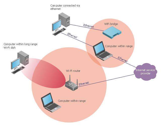
"Long-range Wi-Fi is used for low-cost, unregulated point-to-point computer network connections, as an alternative to other fixed wireless, cellular networks or satellite Internet access.
Wi-Fi networks have a range that's limited by the transmission power, antenna type, the location they're used in, and the environment. A typical wireless router in an indoor point-to-multipoint arrangement using 802.11b or 802.11g and a stock antenna might have a range of 32 metres (105 ft). Outdoor point-to-point arrangements, through use of directional antennas, can be extended with many kilometers between stations." [Long-range Wi-Fi. Wikipedia]
The wireless network diagram example "Long-range Wi-Fi network diagram" was created using the ConceptDraw PRO diagramming and vector drawing software extended with the Wireless Networks solution from the Computer and Networks area of ConceptDraw Solution Park.
Wireless network diagram
"Logical topology, or signal topology, is the arrangement of devices on a computer network and how they communicate with one another. How devices are connected to the network through the actual cables that transmit data, or the physical structure of the network, is called the physical topology. Physical topology defines how the systems are physically connected. It represents the physical layout of the devices on the network. The logical topology defines how the systems communicate across the physical topologies.
Logical topologies are bound to network protocols and describe how data is moved across the network. ...
EXAMPLE : twisted pair Ethernet is a logical bus topology in a physical star topology layout. while IBM's token ring is a logical ring topology, it is physically set up in star topology." [Logical topology. Wikipedia]
This Cisco logical computer network diagram example was created using the ConceptDraw PRO diagramming and vector drawing software extended with the Cisco Network Diagrams solution from the Computer and Networks area of ConceptDraw Solution Park.
Logical network topology diagram

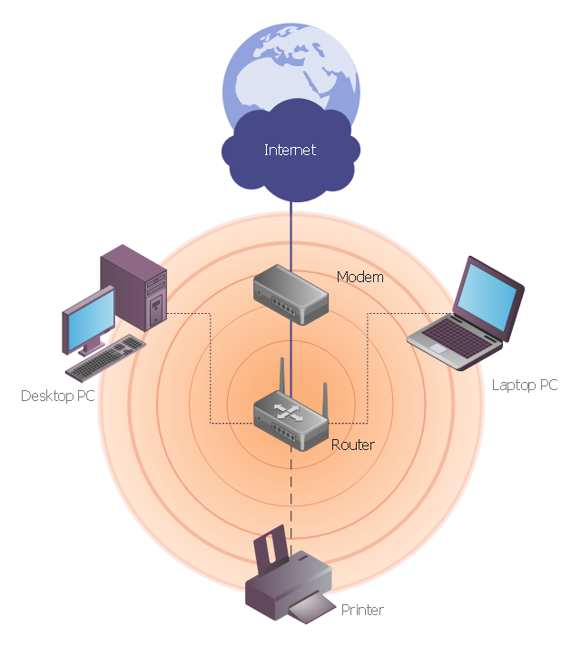
"In computer networking, a wireless access point (AP) is a device that allows wireless devices to connect to a wired network using Wi-Fi, or related standards. The AP usually connects to a router (via a wired network) as a standalone device, but it can also be an integral component of the router itself. ...
With the creation of the wireless Access Point (AP), network users are now able to add devices that access the network with few or no cables. An AP normally connects directly to a wired Ethernet connection and the AP then provides wireless connections using radio frequency links for other devices to utilize that wired connection. Most APs support the connection of multiple wireless devices to one wired connection. Modern APs are built to support a standard for sending and receiving data using, these radio frequencies. Those standards, and the frequencies they use are defined by the IEEE. Most APs use IEEE 802.11 standards." [Wireless access point. Wikipedia]
The wireless network diagram example "Wireless access point" was created using the ConceptDraw PRO diagramming and vector drawing software extended with the Wireless Networks solution from the Computer and Networks area of ConceptDraw Solution Park.
Wireless network diagram
 Computer Network Diagrams
Computer Network Diagrams solution extends ConceptDraw PRO software with samples, templates and libraries of vector icons and objects of computer network devices and network components to help you create professional-looking Computer Network Diagrams, to plan simple home networks and complex computer network configurations for large buildings, to represent their schemes in a comprehensible graphical view, to document computer networks configurations, to depict the interactions between network's components, the used protocols and topologies, to represent physical and logical network structures, to compare visually different topologies and to depict their combinations, to represent in details the network structure with help of schemes, to study and analyze the network configurations, to communicate effectively to engineers, stakeholders and end-users, to track network working and troubleshoot, if necessary.
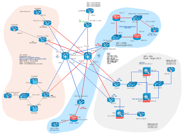
This Cisco network diagram example was drawn on the base of the figure illustrating the post "Cisco Lab 1 : Network Design from the requirement" from the blog "Thai Cisco Club".
"1. Core service porvider by assign P router as P1 and P2, PE router as PE1 - 8 for support CE router of customers.
2. From 1st customer project, assign R1-DMVPN and R2-DWVPN as DMVPN Hub, and R3-DMVPN and R4-DMVPN as DMVPN-Spoke that on different site.
3. From 2nd customer project, assign IP-SEC R1 and IP-SEC R2 as SSO-IP-SEC Router on HQ site, and IP-SEC R3 as branch site that far away."
[thai-cisco-club.blogspot.com/ 2011/ 10/ cisco-lab-1-network-design-from.html]
The diagram example "Cisco network design from the requirement" was created using the ConceptDraw PRO diagramming and vector drawing software extended with the Cisco Network Diagrams solution from the Computer and Networks area of ConceptDraw Solution Park.
Cisco network diagram
Network Printer

"A computer network diagram is a schematic depicting the nodes and connections amongst nodes in a computer network or, more generally, any telecommunications network. ...
Readily identifiable icons are used to depict common network appliances e.g. Router, and the style of lines between them indicate the type of connection. Clouds are used to represent networks external to the one pictured for the purposes of depicting connections between internal and external devices, without indicating the specifics of the outside network. ...
At different scales diagrams may represent various levels of network granularity. At the LAN level, individual nodes may represent individual physical devices, such as hubs or file servers, while at the WAN level, individual nodes may represent entire cities. In addition, when the scope of a diagram crosses the common LAN/ MAN/ WAN boundaries, representative hypothetical devices may be depicted instead of showing all actually existing nodes." [Computer network diagram. Wikipedia]
The computer network diagram template for the ConceptDraw PRO diagramming and vector drawing software is included in the Computer and Networks solution from the Computer and Networks area of ConceptDraw Solution Park.
Computer network diagram template
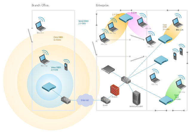
"A wireless local area network (WLAN) links two or more devices using some wireless distribution method (typically spread-spectrum or OFDM radio), and usually providing a connection through an access point to the wider Internet. This gives users the ability to move around within a local coverage area and still be connected to the network. Most modern WLANs are based on IEEE 802.11 standards, marketed under the Wi-Fi brand name. WLANs were once called LAWNs (for local area wireless network) by the Department of Defense." [Wireless LAN. Wikipedia]
The example "Wireless network diagram - Ultra high performance WLANs" was created using the ConceptDraw PRO diagramming and vector drawing software extended with the Wireless Networks solution from the Computer and Networks area of ConceptDraw Solution Park.
The example "Wireless network diagram - Ultra high performance WLANs" was created using the ConceptDraw PRO diagramming and vector drawing software extended with the Wireless Networks solution from the Computer and Networks area of ConceptDraw Solution Park.
WLAN diagram
- Wireless router network diagram | Computer Network Diagrams ...
- Wireless router network diagram | Cisco Routers . Cisco icons ...
- Network Diagram Software Home Area Network | Design elements ...
- Network Gateway Router | Network Diagram Software Home Area ...
- Network Gateway Router | Hotel Network Topology Diagram | How ...
- Computer Network Diagrams | Network Gateway Router | Cisco ...
- Communication network diagram | Network Gateway Router | Cisco ...
- Cisco Routers . Cisco icons, shapes, stencils and symbols | Cisco ...
- Network Gateway Router | Hotel Network Topology Diagram | LAN ...
- Wireless router network diagram | Network Diagram Software Home ...
- Wireless router network diagram | Wireless networks - Vector ...
- How To use Switches in Network Diagram | Star Network Topology ...
- Network Gateway Router | Cisco Intelligent Services Gateway ...
- Network Gateway Router | Computer network - Vector stencils library ...
- Pc Router Diagram
- Network Gateway Router | Network Glossary Definition | Star ...
- Schematic Diagram Of Router
- Network Gateway Router | Network Glossary Definition | Mesh ...
- Wireless router network diagram | Network Gateway Router ...
- Network Gateway Router | Network Diagram Software Home Area ...