 AWS Architecture Diagrams
AWS Architecture Diagrams with powerful drawing tools and numerous predesigned Amazon icons and AWS simple icons is the best for creation the AWS Architecture Diagrams, describing the use of Amazon Web Services or Amazon Cloud Services, their application for development and implementation the systems running on the AWS infrastructure. The multifarious samples give you the good understanding of AWS platform, its structure, services, resources and features, wide opportunities, advantages and benefits from their use; solution’s templates are essential and helpful when designing, description and implementing the AWS infrastructure-based systems. Use them in technical documentation, advertising and marketing materials, in specifications, presentation slides, whitepapers, datasheets, posters, etc.
 Active Directory Diagrams
Active Directory Diagrams solution significantly extends the capabilities of ConceptDraw DIAGRAM software with special Active Directory samples, convenient template and libraries of Active Directory vector stencils, common icons of sites and services, icons of LDPA elements, which were developed to help you in planning and modelling network structures and network topologies, in designing excellently looking Active Directory diagrams, Active Directory Structure diagrams, and Active Directory Services diagram, which are perfect way to visualize detailed structures of Microsoft Windows networks, Active Directory Domain topology, Active Directory Site topology, Organizational Units (OU), and Exchange Server organization.
 Azure Architecture
Azure Architecture solution bundles into one handy tool everything you need to create effective Azure Architecture diagrams. It adds the extra value to versatile ConceptDraw DIAGRAM software and extends the users capabilities with comprehensive collection of Microsoft Azure themed graphics, logos, preset templates, wide array of predesigned vector symbols that covers the subjects such as Azure management, Azure storage, and Azure services, amongst others, and allow you to illustrate Azure Architecture diagrams at any degree of complexity, to present visually your Azure cloud system architecture with professional style, to design Azure cloud topology, to document Windows Azure Architecture and Azure Cloud System Architecture, to visualize the great abilities and work of Microsoft Azure Cloud System and Azure services.
UML Use Case Diagram Example. Registration System

Entity Relationship Diagram Examples


Entity Relationship Software

 HR Flowcharts
Human resource management diagrams show recruitment models, the hiring process and human resource development of human resources.
Campus Area Networks (CAN). Computer and Network Examples


Design Element: Active Directory for Network Diagrams
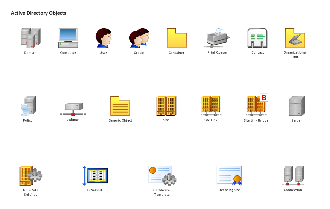
Active Directory Diagram

- Certificate Maker Free Download
- Free Award Certificates Templates To Download
- AWS Architecture Diagrams | Azure Architecture | Windows Azure ...
- Free Download Sign Software
- Wide area network (WAN) topology. Computer and Network ...
- Entity Relationship Diagram Examples | Active Directory Diagrams ...
- UML Deployment Diagram. Design Elements | Design elements ...
- AWS Architecture Diagrams | Design elements - AWS Security ...
- Design elements - Gateways and artifacts BPMN 1.2 | AWS Security ...
- Cars Droing Video Download