Basic Flowchart Symbols and Meaning


Flowchart Definition

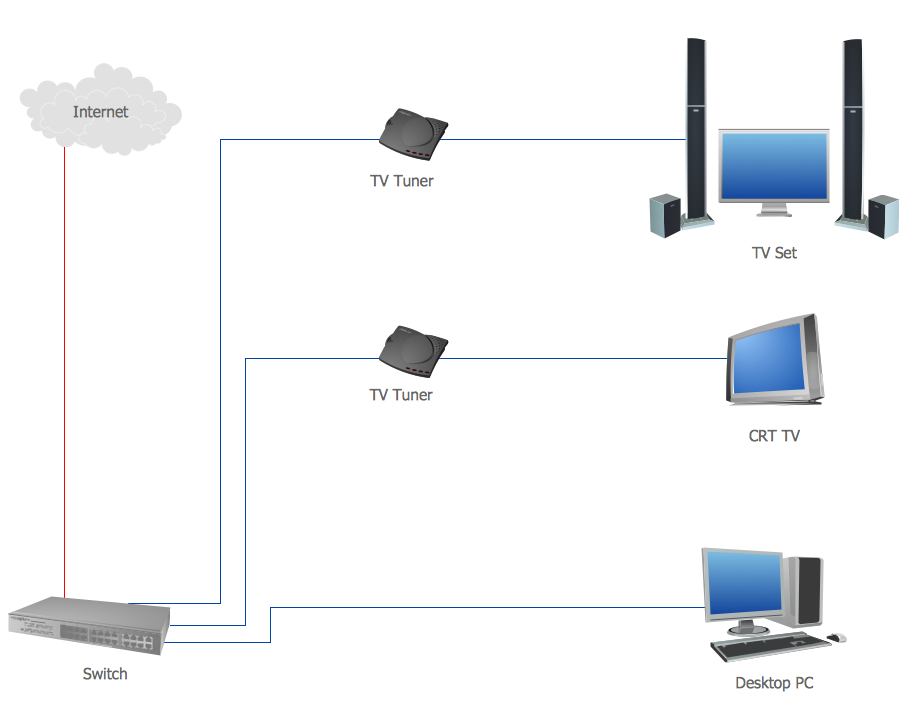
Telecommunication networks. Computer and Network Examples


Diagram of a Basic Computer Network. Computer Network Diagram Example
Metropolitan area networks (MAN). Computer and Network Examples

Physical network. Computer and Network Examples
ERD Symbols and Meanings


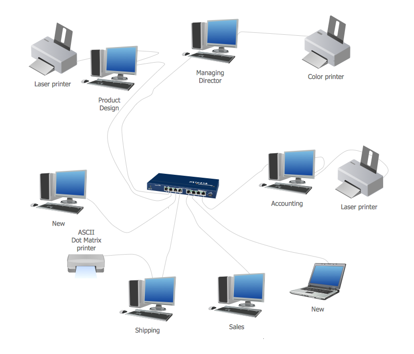
 Computer Network Diagrams
Computer Network Diagrams solution extends ConceptDraw DIAGRAM software with samples, templates and libraries of vector icons and objects of computer network devices and network components to help you create professional-looking Computer Network Diagrams, to plan simple home networks and complex computer network configurations for large buildings, to represent their schemes in a comprehensible graphical view, to document computer networks configurations, to depict the interactions between network's components, the used protocols and topologies, to represent physical and logical network structures, to compare visually different topologies and to depict their combinations, to represent in details the network structure with help of schemes, to study and analyze the network configurations, to communicate effectively to engineers, stakeholders and end-users, to track network working and troubleshoot, if necessary.
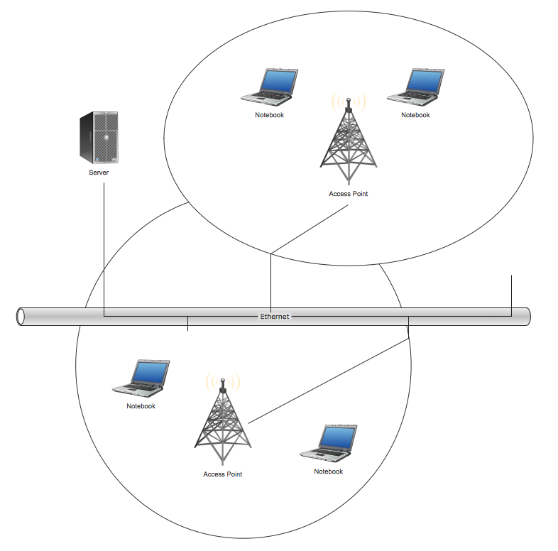
Wireless network. Computer and Network Examples

Wireless Network Topology
- Examples Of Computer Icon And Their Meaning
- Cloud Callout Meaning In Computer
- Computer Ict Gadget And Meaning
- Basic Flowchart Symbols and Meaning | Mathematics | Diagram ...
- Computer Science Flowchart Symbols
- Types of Flowcharts | Basic Flowchart Symbols and Meaning ...
- Computer Architecture Flow Diagram And Definition
- Basic Flowchart Symbols and Meaning | Mcqs On Flowcharting ...
- Definition Man And Diagram
- Basic Flowchart Symbols and Meaning | Diagram of a Basic ...