Electrical Symbols — Power Sources

The vector stencils library "Power sources" contains 9 element symbols of power sources, power supplies and batteries.
Use these shapes for drawing the electrical schematics and electronic circuit diagrams in the ConceptDraw PRO diagramming and vector drawing software extended with the Electrical Engineering solution from the Engineering area of ConceptDraw Solution Park.
www.conceptdraw.com/ solution-park/ engineering-electrical
Battery with polarity labels
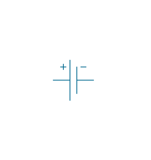
Battery

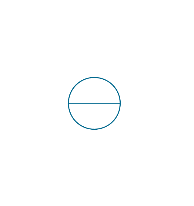
Ideal current source
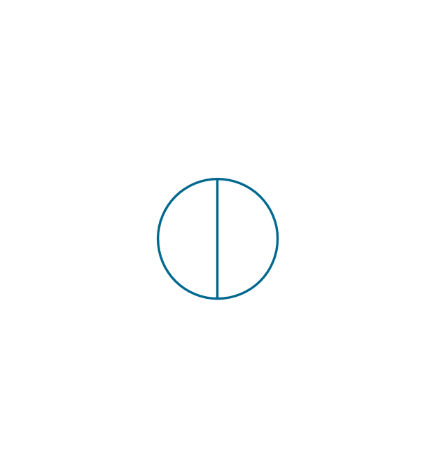
Ideal voltage source
Oscillator

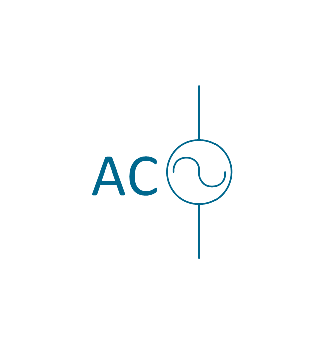
AC current source
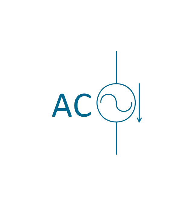
AC voltage source
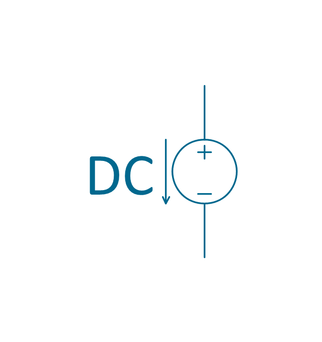
DC current source
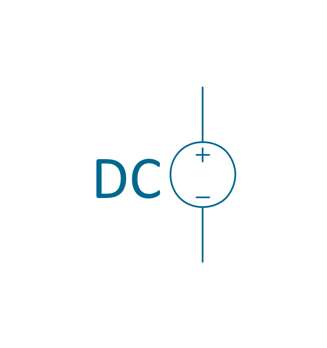
DC voltage source
The vector stencils library "Power sources" contains 9 element symbols of power sources, power supplies and batteries.
Use these shapes for drawing the electrical schematics and electronic circuit diagrams in the ConceptDraw PRO diagramming and vector drawing software extended with the Electrical Engineering solution from the Engineering area of ConceptDraw Solution Park.
www.conceptdraw.com/ solution-park/ engineering-electrical
Use these shapes for drawing the electrical schematics and electronic circuit diagrams in the ConceptDraw PRO diagramming and vector drawing software extended with the Electrical Engineering solution from the Engineering area of ConceptDraw Solution Park.
www.conceptdraw.com/ solution-park/ engineering-electrical
Battery with polarity labels
Battery
Ideal current source
Ideal voltage source
Oscillator
AC current source
AC voltage source
DC current source
DC voltage source
Electrical Symbols — Thermo

Electrical Symbols — Rotating Equipment

Electrical Symbols — Inductors

Electrical Symbols — Switches and Relays

Functional Block Diagram

Electrical Symbols — Qualifying

Electrical Symbols, Electrical Diagram Symbols

- Power sources - Vector stencils library
- Electrical Symbols — Power Sources | Electrical Symbols ...
- Design elements - Power sources | Power sources - Vector stencils ...
- Electrical Symbols — Thermo | Thermo - Vector stencils library ...
- Symbol Of Ideal Dc Voltage Source
- Ac Current Source Symbol
- Electrical Symbols — Power Sources | Design elements ...
- Electrical Symbols, Electrical Diagram Symbols | Electrical Symbols ...
- Power socket outlet layout | Design elements - Power sources ...
- Electrical Symbols — Power Sources | Lamps, acoustics, measuring ...