 Entity-Relationship Diagram (ERD)
Entity-Relationship Diagram (ERD) solution extends ConceptDraw DIAGRAM software with templates, samples and libraries of vector stencils from drawing the ER-diagrams by Chen's and crow’s foot notations.
 Entity-Relationship Diagram (ERD)
An Entity-Relationship Diagram (ERD) is a visual presentation of entities and relationships. That type of diagrams is often used in the semi-structured or unstructured data in databases and information systems. At first glance ERD is similar to a flowch
Draw Network Diagram based on Templates and Examples


Example of DFD for Online Store (Data Flow Diagram)


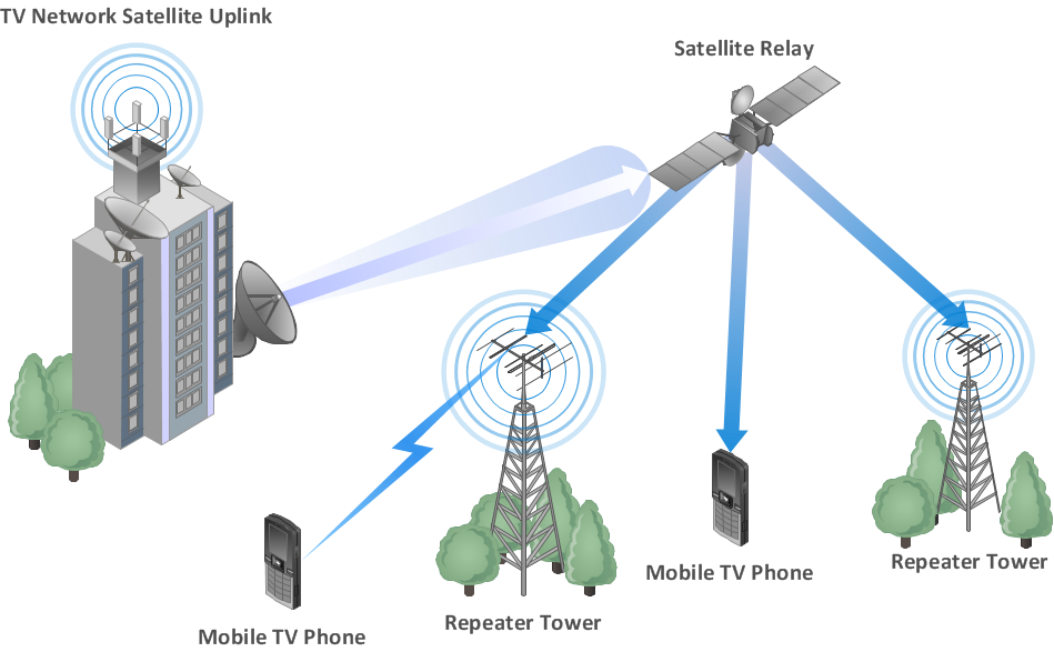
Wireless Network WAN
Create Floor Plans Easily with ConceptDraw DIAGRAM


UML Deployment Diagram. Design Elements

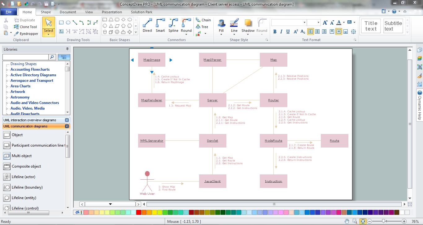
Online Diagram Tool
 Computer Network Diagrams
Computer Network Diagrams solution extends ConceptDraw DIAGRAM software with samples, templates and libraries of vector icons and objects of computer network devices and network components to help you create professional-looking Computer Network Diagrams, to plan simple home networks and complex computer network configurations for large buildings, to represent their schemes in a comprehensible graphical view, to document computer networks configurations, to depict the interactions between network's components, the used protocols and topologies, to represent physical and logical network structures, to compare visually different topologies and to depict their combinations, to represent in details the network structure with help of schemes, to study and analyze the network configurations, to communicate effectively to engineers, stakeholders and end-users, to track network working and troubleshoot, if necessary.
 Network Layout Floor Plans
Network Layout Floor Plans solution extends ConceptDraw DIAGRAM software functionality with powerful tools for quick and efficient documentation the network equipment and displaying its location on the professionally designed Network Layout Floor Plans. Never before creation of Network Layout Floor Plans, Network Communication Plans, Network Topologies Plans and Network Topology Maps was not so easy, convenient and fast as with predesigned templates, samples, examples and comprehensive set of vector design elements included to the Network Layout Floor Plans solution. All listed types of plans will be a good support for the future correct cabling and installation of network equipment.
Best Multi-Platform Diagram Software
 Computers and Communications
Computers and communications solution extends ConceptDraw DIAGRAM software with illustration samples, templates and vector stencils libraries with clip art of computers, control devices, communications, technology, Apple machines.
UML Use Case Diagram Example. Social Networking Sites Project

- Er Diagram For Computer Shop
- Er Diagram For Computer Shop Database
- Er Diagram For Computer Shop Management
- Erd Of Electronic Shop
- Erd In Electronic Shop Management
- Network Layout Floor Plans | Store Layout Software | Computer ...
- Erd Computer Shop Entity Seven
- PM Easy | Entity-Relationship Diagram ( ERD ) | Computer Network ...
- Floor Arrangement For Computershop
- Example of DFD for Online Store (Data Flow Diagram) DFD ...
- Computer Shop Business Plan Pdf
- Entity Relationship Diagram Of Computer Shop Management System
- UML Class Diagram Example - Medical Shop | Computer Network ...
- What Is Dfd In Computer Shop
- UML Class Diagram Example - Medical Shop | UML Use Case ...
- Network Layout Floor Plans | Store Layout Software | How To Create ...
- Furniture Shop For Er Diagram
- Computer Shop Layout Plan
- Er Diagram Online Furniture Shop
- Process Flow Diagram Of Computer Shop