 Mechanical Engineering
This solution extends ConceptDraw DIAGRAM.9 mechanical drawing software (or later) with samples of mechanical drawing symbols, templates and libraries of design elements, for help when drafting mechanical engineering drawings, or parts, assembly, pneumatic,
Technical Drawing Software

Mechanical Drawing Symbols

"Directional control valves are one of the most fundamental parts in hydraulic machinery as well and pneumatic machinery. They allow fluid flow into different paths from one or more sources. They usually consist of a spool inside a cylinder which is mechanically or electrically controlled. The movement of the spool restricts or permits the flow, thus it controls the fluid flow. ...
While working with layouts of hydraulic machinery it is cumbersome to draw actual picture of every valve and other components.instead of pictures symbols are used for variety of components in the hydraulic system to highlight the functional aspects. symbol for directional control valve is made of number of square boxes adjacent to each other depending on the number of positions.connections to the valve are shown on these squares by capital letters.usually they are named only in their normal position and not repeated in other positions.actuation system of the valve is also designated in its symbol." [Directional control valve. Wikipedia]
The Mac template "Pneumatic 5-ported 3-position valve" for the ConceptDraw PRO diagramming and vector drawing software is included in the Mechanical Engineering solution from the Engineering area of ConceptDraw Solution Park.
www.conceptdraw.com/ solution-park/ engineering-mechanical
Pneumatic directional control valve

Mechanical Drawing Software

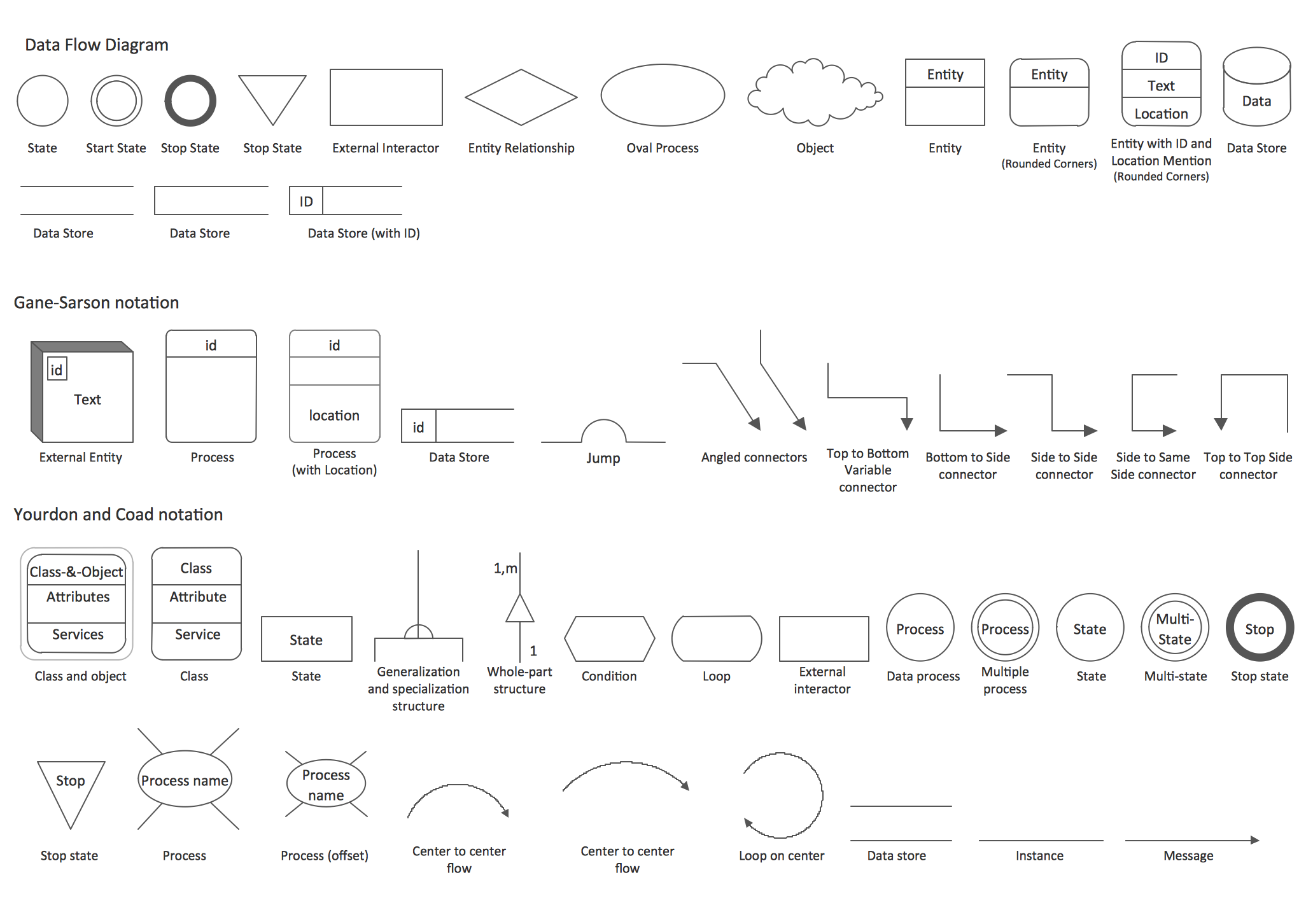
DFD Library — Design elements
UML State Machine Diagram.Design Elements

Interior Design. Piping Plan — Design Elements

Data Flow Diagram Symbols. DFD Library

Circuits and Logic Diagram Software

- Air Compressor Symbols Of Pneumatic System
- Pneumatic Engineering Systems Diagram
- Draw The Symbol That Is Used Pneumatic System
- Design elements - Pneumatic pumps and motors | Pneumatic 5 ...
- Flow Chart Of Pneumatic System
- Engineering | Mechanical Engineering | How To Draw Pneumatic ...
- Sketch Of Basic Elements Of Hydraulik System
- Hydraulic schematic | Hydraulic circuits | Hydraulic 5-ported 3 ...
- Hydraulic And Pneumatic Systems Examples
- Mechanical Drawing Symbols | Pneumatic 5-ported 3-position valve ...