Electrical Symbols, Electrical Diagram Symbols

ERD Symbols and Meanings


Flowchart design. Flowchart symbols, shapes, stencils and icons


Column Chart Template

Wireframing

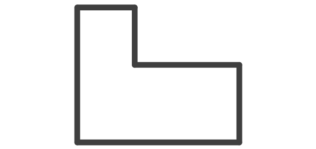
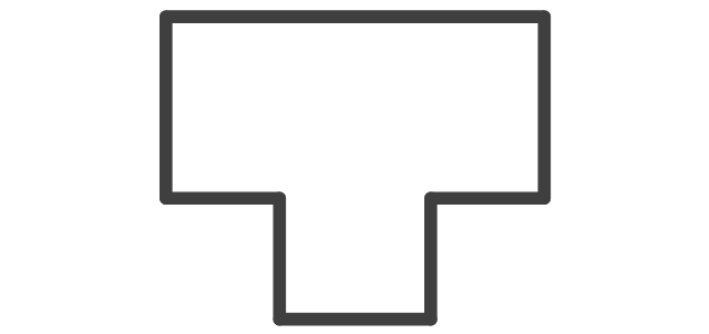
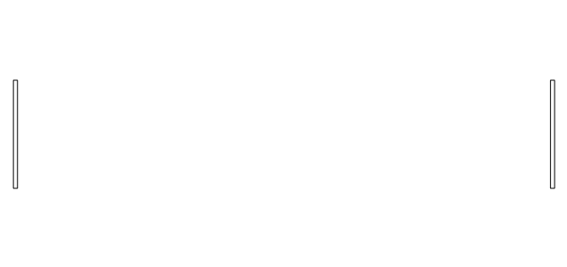
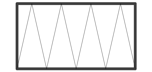
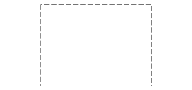
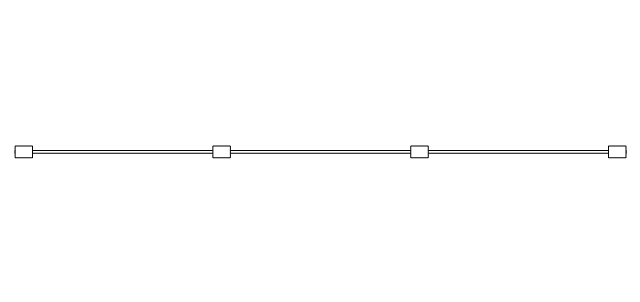
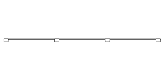
The vector stencils library "Walls, shell and structure" contains 29 shapes of walls, windows, doors, pillars. Use it for drawing architectural blueprints, home and building design, space plans, and construction and house framing diagrams in the ConceptDraw PRO diagramming and vector drawing software extended with the Floor Plans solution from the Building Plans area of ConceptDraw Solution Park.
Wall
Wall 2
Exterior Wall
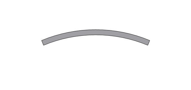
Curved Wall 1
Curved Wall 2
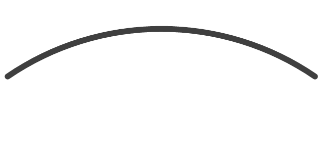
Curved Wall 3
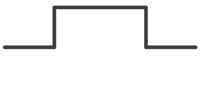
Wall with pocket
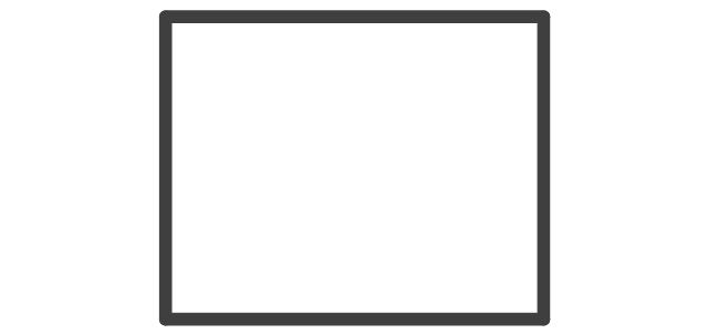
Room
L-Room
T-Room
Room Divider

Opening
Closet
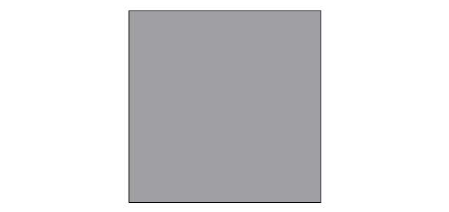
Slab
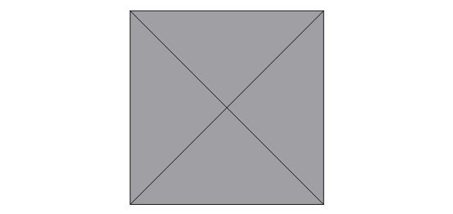
Pilaster

Corner pilaster

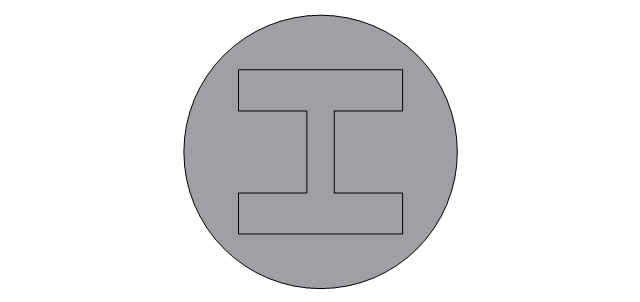
Rectangular column, concrete
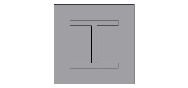
Rectangular column, steel
Rectangular column, wood
Circular column, concrete
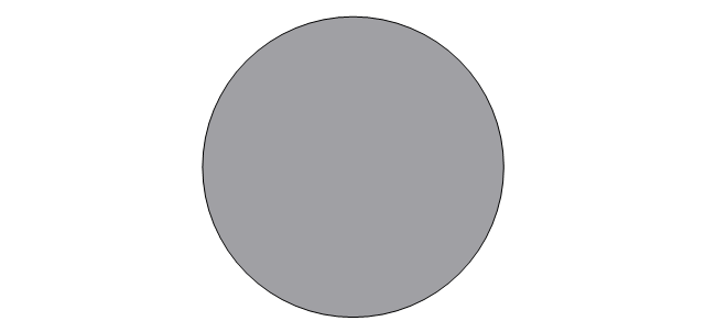
Circular column, steel
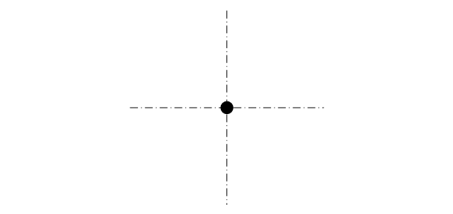
Grid Origin
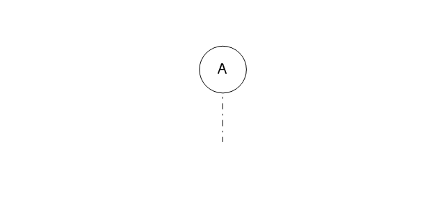
Grid Line
Window wall, inside edge
Window wall, middle
Window wall, outside edge
Curtain wall, inside edge
Curtain wall, middle
Curtain wall, outside edge
Building Drawing Design Element: Piping Plan


Data Modeling Diagram

Network Community Structure. Computer and Network Examples


Structured Systems Analysis and Design Method (SSADM) with ConceptDraw PRO

- Architectural Drawing Symbols Column Slab
- Architectural Symbol Of Column
- Civil Engineering Symbol Column
- Design elements - Walls, shell and structure | Load Bearing Wall ...
- Architecture Wall Symbols And Window
- Symbol Of Pillar On A Building Plan
- Architectural Roofing Symbols
- Symbol Of A Column In A Floor Plan
- Walls, shell and structure - Vector stencils library | Walls, shell and ...
- What Is A Symbol For Showing Curtain In Plan