Design Elements for UML Diagrams

UML Business Process

UML Diagram

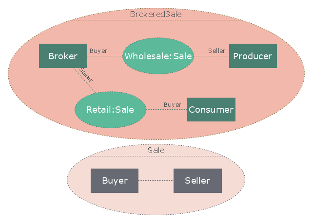
"A broker is an individual or party (brokerage firm) that arranges transactions between a buyer and a seller for a commission when the deal is executed. A broker who also acts as a seller or as a buyer becomes a principal party to the deal. Distinguish agent - one who acts on behalf of a principal. ...
In general a broker is an independent agent used extensively in some industries. A broker's prime responsibility is to bring sellers and buyers together and thus a broker is the third-person facilitator between a buyer and a seller. An example would be a real estate broker who facilitates the sale of a property.
Brokers also can furnish market information regarding prices, products, and market conditions. Brokers may represent either the seller (90% of the time) or the buyer (10%) but not both at the same time. An example would be a stockbroker, who makes the sale or purchase of securities on behalf of his client. Brokers play a huge role in the sale of stocks, bonds, and other financial services." [Broker. Wikipedia]
The UML composite structure diagram example "Sale process" was created using the ConceptDraw PRO diagramming and vector drawing software extended with the Rapid UML solution from the Software Development area of ConceptDraw Solution Park.
UML composite structure diagram
The vector stencils library "UML composite structure diagrams" contains 36 symbols for the ConceptDraw PRO diagramming and vector drawing software.
"The key composite structure entities identified in the UML 2.0 specification are structured classifiers, parts, ports, connectors, and collaborations.
(1) Part : A part represents a role played at runtime by one instance of a classifier or by a collection of instances. The part may only name the role, it may name an abstract superclass, or it may name a specific concrete class. The part can include a multiplicity factor, such as the [0..*] shown for Viewer in the diagram.
(2) Port : A port is an interaction point that can be used to connect structured classifiers with their parts and with the environment. Ports can optionally specify the services they provide and the services they require from other parts of the system. In the diagram, each of the small squares is a port. Each port has a type and is labelled with a name, such as "var", "indVar1", or "view" in the diagram. Ports may contain a multiplicity factor, for example.
Ports can either delegate received requests to internal parts, or they can deliver these directly to the behavior of the structured classifier that the port is contained within. Public ports that are visible in the environment are shown straddling the boundary, while protected ports that are not visible in the environment are shown inside the boundary. All the ports in the diagram are public, except for the view port along the right boundary of FibonacciSystem.
(3) Connector : A connector binds two or more entities together, allowing them to interact at runtime. The connector is shown as a line between some combination of parts, ports and structured classifiers. The diagram shows three connectors between ports, and one connector between a structured classifier and a part.
(4) Collaboration : A collaboration is generally more abstract than a structured classifier. It is shown as a dotted oval containing roles that instances can play in the collaboration.
(5) Structured classifier : A StructuredClassifier represents a class, often an abstract class, whose behavior can be completely or partially described through interactions between parts." [Composite structure diagram. Wikipedia]
The example "Design elements - UML composite structure diagrams" is included in the Rapid UML solution from the Software Development area of ConceptDraw Solution Park.
UML composite structure diagram symbols

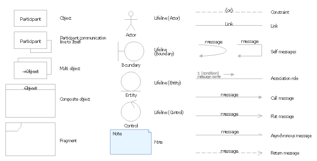
The vector stencils library "UML communication diagrams" contains 23 symbols for the ConceptDraw PRO diagramming and vector drawing software.
"... communication diagrams use the free-form arrangement of objects and links as used in Object diagrams. In order to maintain the ordering of messages in such a free-form diagram, messages are labeled with a chronological number and placed near the link the message is sent over. Reading a communication diagram involves starting at message 1.0, and following the messages from object to object." [Communication diagram. Wikipedia]
The example "Design elements - UML communication diagrams" is included in the Rapid UML solution from the Software Development area of ConceptDraw Solution Park.
UML communication diagram symbols
Sequence Diagram Tool
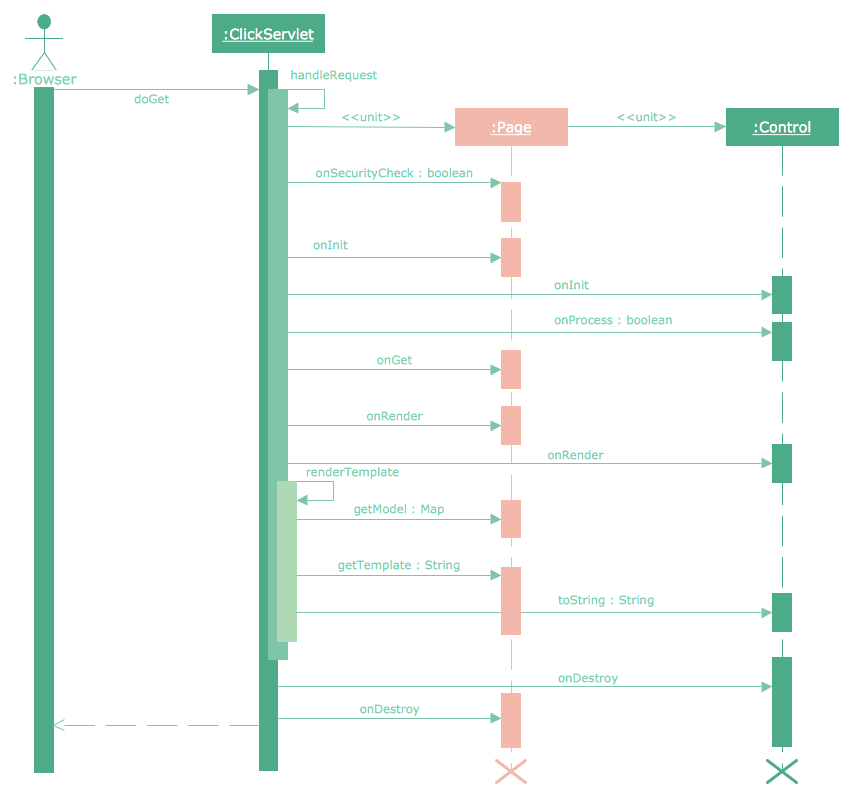
"The client–server model of computing is a distributed application structure that partitions tasks or workloads between the providers of a resource or service, called servers, and service requesters, called clients. Often clients and servers communicate over a computer network on separate hardware, but both client and server may reside in the same system. A server host runs one or more server programs which share their resources with clients. A client does not share any of its resources, but requests a server's content or service function. Clients therefore initiate communication sessions with servers which await incoming requests.
Examples of computer applications that use the client–server model are Email, network printing, and the World Wide Web." [Client–server model. Wikipedia]
The UML communication diagram example "Client server access" was created using the ConceptDraw PRO diagramming and vector drawing software extended with the Rapid UML solution from the Software Development area of ConceptDraw Solution Park.
UML communication diagram

Systems Engineering

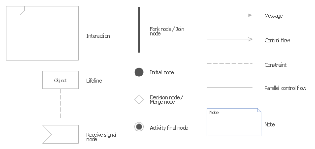
The vector stencils library "UML interaction overview diagrams" contains 13 symbols for the ConceptDraw PRO diagramming and vector drawing software.
"Interaction Overview Diagram is one of the fourteen types of diagrams of the Unified Modeling Language (UML), which can picture a control flow with nodes that can contain interaction diagrams.
The interaction overview diagram is similar to the activity diagram, in that both visualize a sequence of activities. The difference is that, for an interaction overview, each individual activity is pictured as a frame which can contain a nested interaction diagrams." [Interaction overview diagram. Wikipedia]
"Interaction diagrams.
Interaction diagrams, a subset of behavior diagrams, emphasize the flow of control and data among the things in the system being modeled:
(1) Communication diagram: shows the interactions between objects or parts in terms of sequenced messages. They represent a combination of information taken from Class, Sequence, and Use Case Diagrams describing both the static structure and dynamic behavior of a system.
(2) Interaction overview diagram: provides an overview in which the nodes represent interaction diagrams.
(3) Sequence diagram: shows how objects communicate with each other in terms of a sequence of messages. Also indicates the lifespans of objects relative to those messages.
(4) Timing diagrams: a specific type of interaction diagram where the focus is on timing constraints." [Unified Modeling Language. Wikipedia]
The example "Design elements - UML interaction overview diagrams" is included in the Rapid UML solution from the Software Development area of ConceptDraw Solution Park.
UML interaction overview diagram symbols
Booch OOD Diagram

 Event-driven Process Chain Diagrams
Event-Driven Process Chain Diagrams solution extends ConceptDraw DIAGRAM functionality with event driven process chain templates, samples of EPC engineering and modeling the business processes, and a vector shape library for drawing the EPC diagrams and EPC flowcharts of any complexity. It is one of EPC IT solutions that assist the marketing experts, business specialists, engineers, educators and researchers in resources planning and improving the business processes using the EPC flowchart or EPC diagram. Use the EPC solutions tools to construct the chain of events and functions, to illustrate the structure of a business process control flow, to describe people and tasks for execution the business processes, to identify the inefficient businesses processes and measures required to make them efficient.
About UML

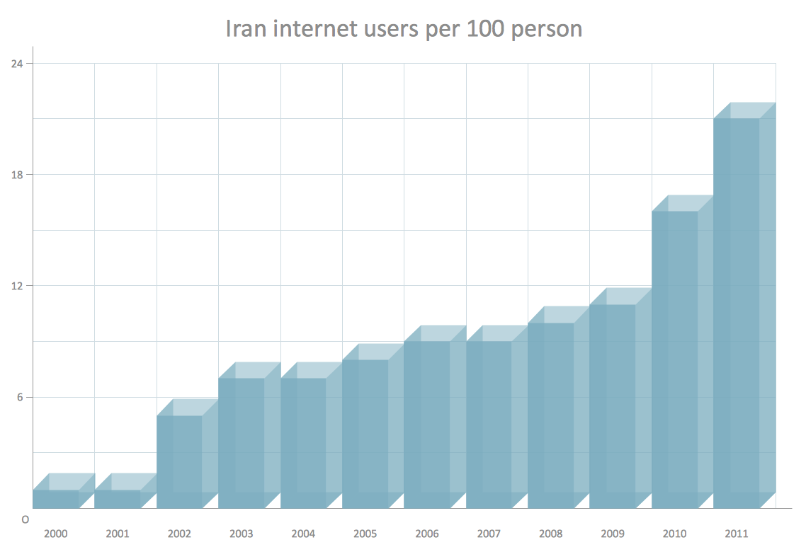
Column Chart Software
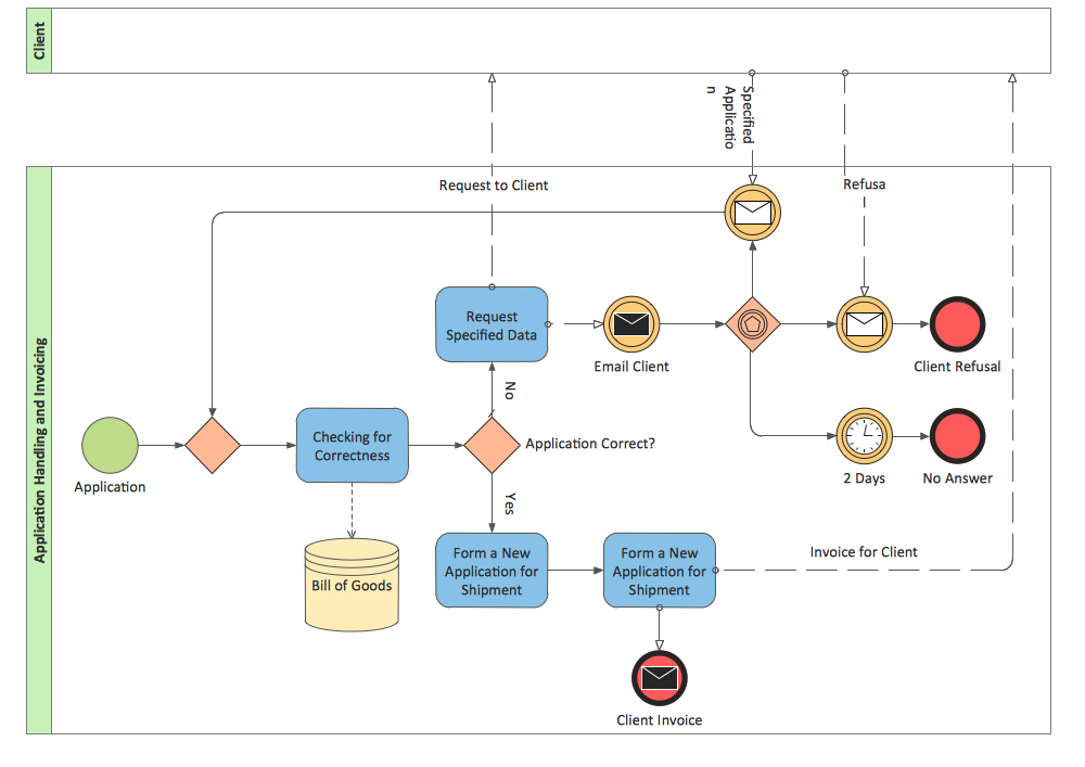
BPMN 2.0
- Diagramming Software for Design UML Collaboration Diagrams ...
- Collaboration Diagram Wiki
- Diagramming Software for Design UML Collaboration Diagrams ...
- Diagramming Software for Design UML Collaboration Diagrams ...
- UML Diagram | Design Elements for UML Diagrams | Jacobson Use ...
- UML Collaboration Diagram . Design Elements | UML Sequence ...
- UML for Bank | ATM UML Diagrams | Bank UML Diagram | Uml Bank
- Collaboration Diagram For Bug Tracking
- Diagramming Software for Design UML Communication Diagrams ...
- UML Diagram | Design Elements for UML Diagrams | UML Business ...
- Wiki Uml Diagrams
- Design elements - Bank UML communication diagram | Design ...
- UML Sequence Diagram . Design Elements | UML Collaboration ...
- UML Diagram | Purchase order processing UML activity diagram ...
- UML communication diagram - Client server access | Diagramming ...
- UML Object Diagram . Design Elements | UML Collaboration ...
- UML Diagram | UML Tool & UML Diagram Examples | State ...
- BPM life cycle | Identifying Quality Management System | UML ...
- Design elements - UML communication diagrams | UML ...
- Diagramming Software for Design UML Communication Diagrams