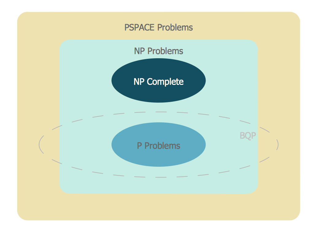
Venn Diagram Examples for Problem Solving. Computer Science. Chomsky Hierarchy

 Jackson Structured Programming (JSP) Diagrams
The Jackson Structured Programming (JSP) Diagram solution extends the functionality and drawing abilities of the ConceptDraw DIAGRAM software with set of illustrative JSP diagrams samples and large variety of predesigned vector objects of actions, processes, procedures, selection, iteration, as well as arrows and connectors to join the objects during Jackson structured development and designing Jackson structured programming diagrams, JSP diagram, Jackson structure diagram (JSD), Program structure diagram. The powerful abilities of this solution make the ConceptDraw DIAGRAM ideal assistant for programmers, software developers, structural programmers, computer engineers, applications constructors, designers, specialists in structured programming and Jackson systems design, and other technical, computer and software specialists.
IDEF4 Standard

UML Flowchart Symbols

UML Class Diagram Notation

IDEF0 standard with ConceptDraw DIAGRAM

Venn Diagram Examples for Problem Solving
UML Diagrams with ConceptDraw DIAGRAM

Design Elements for UML Diagrams

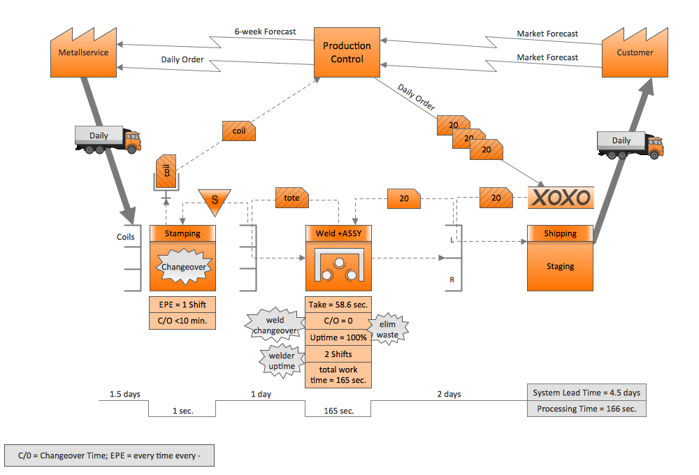
Quality Engineering Diagrams
- Venn Diagram Examples for Problem Solving. Computer Science ...
- Bank System | Banking System | Class UML Diagram for Bank ...
- Data Flow Diagram Examples | Types of Flowcharts | IDEF4 ...
- Program Structure Diagram | Data structure diagram with ...
- Login and registration processing | Flowchart | Basic Flowchart ...
- Tuning-fork style diagram of the Hubble sequence | Expanded ...
- Examples of Reed-Kellogg diagrams | The Reed-Kellogg system ...
- Basic Flowchart Symbols and Meaning | Process Flowchart | UML ...
- Example of DFD for Online Store (Data Flow Diagram ) | UML Class ...
- Process Flowchart | Electrical Symbols — Maintenance ...