The vector stencils library "Transmission paths" contains 43 symbols of power transmission paths, electronic circuits, bus connectors and elbows, terminals, junctions, and concentrators.
Use it to annotate electrical diagrams, electronic schematics and circuit diagrams.
"A physical medium in data communications is the transmission path over which a signal propagates.
Many transmission media are used as communications channel.
For telecommunications purposes in the United States, Federal Standard 1037C, transmission media are classified as one of the following:
(1) Guided (or bounded) - waves are guided along a solid medium such as a transmission line.
(2) Wireless (or unguided) - transmission and reception are achieved by means of an antenna.
One of the most common physical medias used in networking is copper wire. Copper wire to carry signals to long distances using relatively low amounts of power. The unshielded twisted pair (UTP) is eight strands of copper wire, organized into four pairs.
Another example of a physical medium is optical fiber, which has emerged as the most commonly used transmission medium for long-distance communications. Optical fiber is a thin strand of glass that guides light along its length.
Multimode and single mode are two types of commonly used optical fiber. Multimode fiber uses LEDs as the light source and can carry signals over shorter distances, about 2 kilometers. Single mode can carry signals over distances of tens of miles.
Wireless media may carry surface waves or skywaves, either longitudinally or transversely, and are so classified.
In both communications, communication is in the form of electromagnetic waves. With guided transmission media, the waves are guided along a physical path; examples of guided media include phone lines, twisted pair cables, coaxial cables, and optical fibers. Unguided transmission media are methods that allow the transmission of data without the use of physical means to define the path it takes. Examples of this include microwave, radio or infrared. Unguided media provide a means for transmitting electromagnetic waves but do not guide them; examples are propagation through air, vacuum and seawater.
The term direct link is used to refer to the transmission path between two devices in which signals propagate directly from transmitters to receivers with no intermediate devices, other than amplifiers or repeaters used to increase signal strength. This term can apply to both guided and unguided media.
A transmission may be simplex, half-duplex, or full-duplex.
In simplex transmission, signals are transmitted in only one direction; one station is a transmitter and the other is the receiver. In the half-duplex operation, both stations may transmit, but only one at a time. In full duplex operation, both stations may transmit simultaneously. In the latter case, the medium is carrying signals in both directions at same time." [Transmission medium. Wikipedia]
The shapes example "Design elements - Transmission paths" was drawn using the ConceptDraw PRO diagramming and vector drawing software extended with the Electrical Engineering solution from the Engineering area of ConceptDraw Solution Park.
Transmission path symbols

Electrical Symbols, Electrical Schematic Symbols

Telecommunication networks. Computer and Network Examples


The vector stencils library "VHF UHF SHF" contains 52 symbols for VHF, UHF, and SHF circuit design, including capacitance measurers, nonreciprocal devices, modulators, phase shifters, field polarization devices, and filters.
"Very high frequency (VHF) is the ITU-designated range of radio frequency electromagnetic waves from 30 MHz to 300 MHz, with corresponding wavelengths of one to ten meters. Frequencies immediately below VHF are denoted high frequency (HF), and the next higher frequencies are known as ultra high frequency (UHF).
Common uses for VHF are FM radio broadcasting, television broadcasting, land mobile stations (emergency, business, private use and military), long range data communication up to several tens of kilometres with radio modems, amateur radio, and marine communications. Air traffic control communications and air navigation systems (e.g. VOR, DME & ILS) work at distances of 100 kilometres or more to aircraft at cruising altitude.
VHF was previously used for analog television stations in the US." [Very high frequency. Wikipedia]
"Ultra-high frequency (UHF) designates the ITU radio frequency range of electromagnetic waves between 300 MHz and 3 GHz (3,000 MHz), also known as the decimetre band or decimetre wave as the wavelengths range from one to ten decimetres; that is 1 decimetre to 1 metre. Radio waves with frequencies above the UHF band fall into the SHF (super-high frequency) or microwave frequency range. Lower frequency signals fall into the VHF (very high frequency) or lower bands. UHF radio waves propagate mainly by line of sight; they are blocked by hills and large buildings although the transmission through building walls is high enough for indoor reception. They are used for television broadcasting (digital and analogue), cordless phones, walkie-talkies, satellite communication, and numerous other applications.
The IEEE defines the UHF radar band as frequencies between 300 MHz and 1 GHz. Two other IEEE radar band overlap the ITU UHF band: the L band between 1 and 2 GHz and the S band between 2 and 4 GHz." [Ultra high frequency. Wikipedia]
"Super high frequency (or SHF) is the ITU designation for radio frequencies (RF) in the range of 3 GHz and 30 GHz. This band of frequencies is also known as the centimetre band or centimetre wave as the wavelengths range from ten to one centimetres. These frequencies fall within the microwave band, so radio waves with these frequencies are called microwaves. The small wavelength of microwaves allows them to be directed in narrow beams by aperture antennas such as parabolic dishes, so they are used for point-to-point communication and data links, and for radar. This frequency range is used for most radar transmitters, microwave ovens, wireless LANs, cell phones, satellite communication, microwave radio relay links, and numerous short range terrestrial data links. The commencing wireless USB technology will be using approximately 1/ 3 of this spectrum.
Frequencies in the SHF range are often referred to by their IEEE radar band designations: S, C, X, Ku, K, or Ka band, or by similar NATO or EU designations." [Super high frequency. Wikipedia]
The shapes example "Design elements - VHF UHF SHF" was drawn using the ConceptDraw PRO diagramming and vector drawing software extended with the Electrical Engineering solution from the Engineering area of ConceptDraw Solution Park.
VHF, UHF, SHF symbols

Network Diagram Software. LAN Network Diagrams. Physical Office Network Diagrams

Star Network Topology


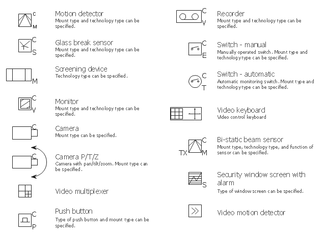
The vector stencils library Video surveillance contains 15 symbols of electronic closed-circuit television (CCTV) equipment, digital video cameras and recording devices and covert video equipment.
"Closed-circuit television (CCTV) is the use of video cameras to transmit a signal to a specific place, on a limited set of monitors. It differs from broadcast television in that the signal is not openly transmitted, though it may employ point to point (P2P), point to multipoint, or mesh wireless links. Though almost all video cameras fit this definition, the term is most often applied to those used for surveillance in areas that may need monitoring such as banks, casinos, airports, military installations, and convenience stores.
In industrial plants, CCTV equipment may be used to observe parts of a process from a central control room, for example when the environment is not suitable for humans. CCTV systems may operate continuously or only as required to monitor a particular event. A more advanced form of CCTV, utilizing digital video recorders (DVRs), provides recording for possibly many years, with a variety of quality and performance options and extra features (such as motion-detection and email alerts). More recently, decentralized IP cameras, some equipped with megapixel sensors, support recording directly to network-attached storage devices, or internal flash for completely stand-alone operation. Surveillance of the public using CCTV is particularly common in many areas around the world." [Closed-circuit television. Wikipedia]
Use the design elements library Video surveillance to design the layout plans of security and access systems, and internal and external video surveillance and security control monitoring systems using the ConceptDraw PRO diagramming and vector drawing software.
The shapes library Video surveillance is included in the Security and Access Plans solution from the Building Plans area of ConceptDraw Solution Park.
Video surveillance symbols
Cisco Products Additional. Cisco icons, shapes, stencils and symbols

3D Network Diagram Software

Network Glossary Definition

 Electrical Engineering
This solution extends ConceptDraw DIAGRAM.9.5 (or later) with electrical engineering samples, electrical schematic symbols, electrical diagram symbols, templates and libraries of design elements, to help you design electrical schematics, digital and analog
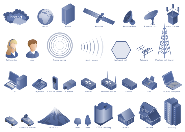
"A telecommunications network is a collection of terminal nodes, links and any intermediate nodes which are connected so as to enable telecommunication between the terminals. The transmission links connect the nodes together. The nodes use circuit switching, message switching or packet switching to pass the signal through the correct links and nodes to reach the correct destination terminal. Each terminal in the network usually has a unique address so messages or connections can be routed to the correct recipients. The collection of addresses in the network is called the address space. Examples of telecommunications networks are: computer networks, Internet, telephone network, global Telex network, aeronautical ACARS network." [Telecommunications network. Wikipedia]
The example "Design elements - Telecommunication networks" was created using the ConceptDraw PRO diagramming and vector drawing software extended with the Telecommunication Network Diagrams solution from the Computer and Networks area of ConceptDraw Solution Park.
The example "Design elements - Telecommunication networks" was created using the ConceptDraw PRO diagramming and vector drawing software extended with the Telecommunication Network Diagrams solution from the Computer and Networks area of ConceptDraw Solution Park.
Telecom diagram symbols
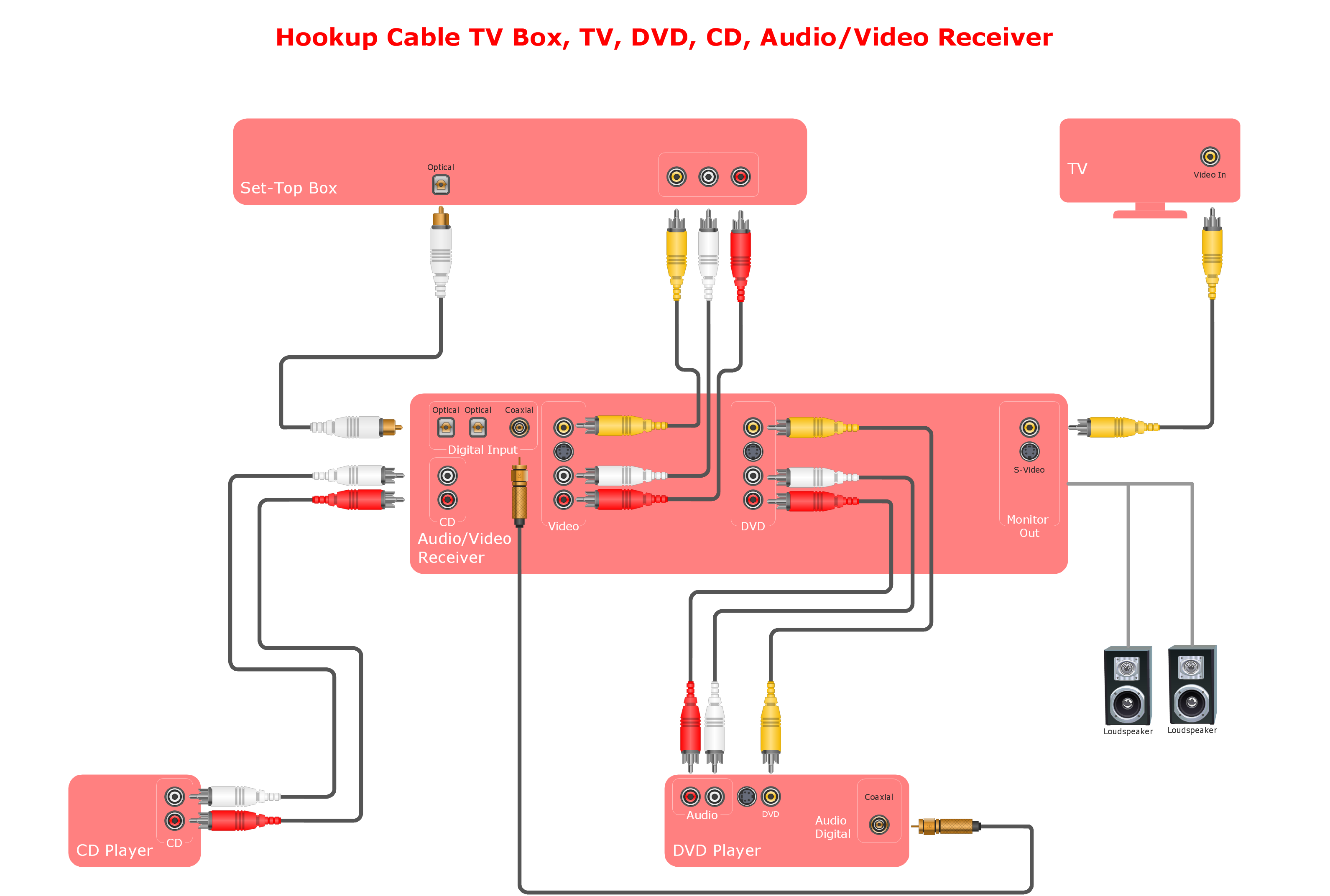
Audio and Video Connections Explained
Social Media Marketing Infographic

HelpDesk
How to Create a CCTV Diagram

- Design elements - Transmission paths | Solid State Schematic ...
- Design elements - Transmission paths | Electrical Symbols ...
- Symbols For Transmission Path
- Electrical Diagram Symbols | Electrical Schematic Symbols | Wiring ...
- Optical Schematic Symbols
- Electrical Diagram Symbols | Electrical Schematic Symbols | Wiring ...
- Circuit Diagram Symbols For An Amplifier
- Electrical Symbols, Electrical Schematic Symbols | Electrical ...
- Telecommunication Network Diagrams | Design elements ...
- Swim Lane Flowchart Symbols | Social Media Flowchart Symbols ...
- Electrical Symbols, Electrical Schematic Symbols | Design elements ...
- Electrical Communication Symbols
- Power Schematic Symbols
- Symbols Of Various Transmitter
- Electrical Symbols , Electrical Diagram Symbols | How To use House ...
- Best Flowchart Software and Flowchart Symbols | Swim Lane ...
- Electrical Drawing Software and Electrical Symbols | Electrical ...
- Radio Waves Symbols
- Design elements - Transmission paths | Bus Network Topology ...
- Symbol Of Telecommunication Engineering