Interior Design. Piping Plan — Design Elements

Electrical Symbols — Electrical Circuits

The vector stencils library "Valves" contains 91 symbols of valves. Use it for drawing plumbing and piping plans, schematic diagrams and blueprints of industrial piping systems; process, vacuum, and fluids piping; hydraulics piping; air and gas piping; materials distribution; and liquid transfer systems in the ConceptDraw PRO diagramming and vector drawing software extended with the Plumbing and Piping Plans solution from the Building Plans area of ConceptDraw Solution Park.
In-line valve

3-way valve

4-way valve

Screw-down valve

Lock-shield valve

Reel valve

Relief valve

Relief valve 2

Relief valve 3

Relief valve 4

Angle valve

Angle valve 2

Angle valve 3

Angle valve 4

Check valve

Check valve 2

Screwdown valve

Float operated valve

Float operated valve 2

Flanged valve

Flanged valve 2

Butterfly valve

Butterfly valve 2

Globe valve

Globe valve 2

Globe valve 3

Needle valve

Needle valve 2

Needle valve 3

Needle valve 4

Diaphragm valve

Diaphragm valve 2

Diaphragm valve 3

Wedge gate valve

Parallel side valve

Gate valve

Ball valve

Ball valve 2

Ball valve 3

Powered control valve

Powered control valve 2

Powered control valve 3

Relief angle valve, pressure

Relief angle valve, vacuum

Reducing valve

Reducing valve 2

Plug valve

Plug valve 2

Plug valve, straight through

3-way plug valve

Plug valve, T-port

Plug valve, L-port

3-way plug valve

3-way plug valve 2

3-way plug valve 3

3-way plug valve, T-port

3-way plug valve, L-port

Mixing valve

Characterized port valve

Manual isolation

Power signal

Statically loaded

Spring loaded

Spring loaded 2

Remote control

Diaphragm

Diaphragm, positioner

Chain operated

Gear operated

Solenoid

Weight loaded

Weight loaded 2

Weight loaded 3

Float operated

Float operated 2

Dash-pot

Dash-pot 2

Piston

Quick opening

Quick opening 2

Quick closing

Quick closing 2

Connecting unit

Connecting unit 2

Connecting unit 3

Motor element

Motor element, opens on failure

Motor element, closes on failure

Motor element, retains position on fail

Motor element, safe direction

Regulating

The vector stencils library "Pipes 2" contains 48 symbols of pipes. Use it for drawing plumbing and piping building plans, schematic diagrams, blueprints, or technical drawings of waste water disposal systems, hot and cold water supply systems in the ConceptDraw PRO diagramming and vector drawing software extended with the Plumbing and Piping Plans solution from the Building Plans area of ConceptDraw Solution Park.
Crossing
Junction
Basic support
Guide 1
Guide 2
Guide 3
Stopper
Anchor
Support / anchor
Hunger
Cross
Double branch
Jacketed
Sleeved
Sleeve joint
Expansion sleeve joint
Lagged
Bellows
Flow indication
Flow indication 2
Reducer
Reducer,arrow
Pipe bore change
Flexibility provision
Sleeve extension
Flow restrictor
Elbow 45
Elbow 90
Heated or cooled
Pneumatic line
Signal line
Electric line
Hydraulic line
Capillary line
Internal connection
Route radiation
Mechanical linkage
Electrical device
Vibratory device
Weight device
Spray device
Rotary motion
Stirring / fan
Access points
Trap
Expansion loop
Flexible hose
Flexible hose, flanged
The vector stencils library "Valves and fittings" contains 104 symbols of valve components.
Use these icons for drawing industrial piping systems; process, vacuum, and fluids piping; hydraulics piping; air and gas piping; materials distribution; and liquid transfer systems in the ConceptDraw PRO software extended with the Chemical and Process Engineering solution from the Chemical and Process Engineering area of ConceptDraw Solution Park.
www.conceptdraw.com/ solution-park/ engineering-chemical-process
Electrically bonded

Bursting disc

Flame arrester

Strainer

Separator

Exhaust silencer

Bell mouth

Exhaust head

Hydrant

Drain silencer

Liquid seal open/closed

Y strainer

Gate valve

Globe valve

Globe valve 2

Globe valve 3

Screw-down valve

Lock-shield valve

Reel valve

Check valve

Check valve 2

Check valve 3

Screw-down check valve

Stop check valve

Diaphragm valve

Diaphragm valve 2

Diaphragm valve 3

Powered valve

Powered valve 2

Powered valve 3

Needle valve

Needle valve 2

Needle valve 3

Relief valve

Relief valve 2

Relief valve 3

Angle valve

Angle valve 2

Angle valve 3

Angle valve 4

Float operated valve

Float operated valve 2

Flanged valve

Butterfly valve

Butterfly valve 2

Wedge gate valve

Parallel slide valve

Ball valve

Ball valve 2

Ball valve 3

Relief angle valve vacuum

Relief angle valve pressure

Reducing valve

Reducing valve 2

Plug valve 3 way

Plug valve L point

Plug valve 2

Plug valve

Plug valve straight through

Plug valve T point

3-way plug valve

3-way plug valve 2

3-way plug valve 3

Mixing valve

Valve Manifold

Characterized port valve

Reducer

Reducer 2

General joint

Butt weld

Butt weld 2

Butt weld 3

Butt weld 4

Flanged/ bolted

Soldered / solvent

Soldered / solvent 2

Screwed joint

Screwed joint 2

Screwed joint 3

Socket and spigot

Socket and spigot 2

Socket and spigot 3

Sleeve

Sleeve 2

Screwed sleeve

Screwed sleeve 2

Socket weld

Socket weld 2

Swivel joint

Swivel joint 2

Swivel joint 3

End cap

End cap butt welded

End cap screwed

End cap socket and spigot

End cap fillet welded

End cap screwed and plugged

End cap quick release

End cap flanged and bolted

End cap flanged and bolted 2

Electrically insulated

Tundish

Syphon drain

Open vent

This HVAC schematics sample depicts the house cool mode of central air pool heater. It was drawn on the base of the HVAC schematics in the post "Central Air Pool Heater" from the Nathan Stratton's blog.
"With House Cool Mode, hot gas leaves the compressor runs through the reversing value into the condenser where it condenses into a liquid. Valve #1 is ON so liquid is able to leave the outside unit and run through the filter dryer and site glass into the evaporator upstairs in the house where the liquid flashes into a gas as it passes through the expansion valve and absorbs heat from the air passing through the evaporator. The cold gas travels downstairs and outside to the compressor and the cycle starts all over again." [robotics.net/ projects/ central-air-pool-heater/ ]
The HVAC schematics example "Central air pool heater" was created using the ConceptDraw DIAGRAM diagramming and vector drawing software extended with the HVAC Plans solution from the Building Plans area of ConceptDraw Solution Park.
HVAC schematics

The vector stencils libraries "Pipes 1" and "Pipes 2" contain 28 and 48 pipe, tubing and fitting symbols, respectively.
"Pipe is hollow cylinder used to conduct or transfer fluids (liquids and gases) from one place to other place. The main difference between pipe and tube is the critical dimension used to describe the pipe size or the tube size. For pipe, internal diameter (ID) roughly corresponds to the nominal pipe size for standard wall thickness. For tube, the outer diameter (OD) closely corresponds to the tube size. In current European standards pipes and tubes are nowadays described as outside diameter by wall thickness. The three standard types of pipe ends used in the piping industriesare; Plain Ends (PE), Threaded Ends (TE) and Beveled Ends (BE). In the past, many types of material have been used in conveying water from one point to another. Masonry and wood were probably the first materials used. Plastics are the newest, and are now being used quite extensively." [Piping. Wikipedia]
Use the design elements libraries "Pipes 1" and "Pipes 2" for drawing plumbing and piping building plans, schematic diagrams, blueprints, or technical drawings of waste water disposal systems, hot and cold water supply systems using the ConceptDraw PRO diagramming and vector drawing software.
The shapes libraries "Pipes 1" and "Pipes 2" are contained in the Plumbing and Piping Plans solution from the Building Plans area of ConceptDraw Solution Park.
Piping symbols
.png--diagram-flowchart-example.png)
The vector stencils library "Vessels" contains 40 symbols of vessels, containers, tanks, drums, and basins.
Use these shapes for drawing process flow diagrams (PFD), materials handling systems, and feed systems in industrial and manufacturing processes.
"A pressure vessel is a closed container designed to hold gases or liquids at a pressure substantially different from the ambient pressure.
The pressure differential is dangerous and fatal accidents have occurred in the history of pressure vessel development and operation. Consequently, pressure vessel design, manufacture, and operation are regulated by engineering authorities backed by legislation. For these reasons, the definition of a pressure vessel varies from country to country, but involves parameters such as maximum safe operating pressure and temperature." [Pressure vessel. Wikipedia]
The example "Design elements - Vessels" was created using the ConceptDraw PRO diagramming and vector drawing software extended with the Chemical and Process Engineering solution from the Engineering area of ConceptDraw Solution Park.
Vessel symbols

 Plumbing and Piping Plans
Plumbing and Piping Plans solution extends ConceptDraw DIAGRAM.2.2 software with samples, templates and libraries of pipes, plumbing, and valves design elements for developing of water and plumbing systems, and for drawing Plumbing plan, Piping plan, PVC Pipe plan, PVC Pipe furniture plan, Plumbing layout plan, Plumbing floor plan, Half pipe plans, Pipe bender plans.
The vector stencils library "Vessels" contains 40 symbols of vessels, containers, tanks, drums, and basins.
Use it for drawing industrial and manufacturing process flow diagrams, materials handling systems, and feed systems in the ConceptDraw PRO software extended with the Chemical and Process Engineering solution from the Chemical and Process Engineering area of ConceptDraw Solution Park.
www.conceptdraw.com/ solution-park/ engineering-chemical-process
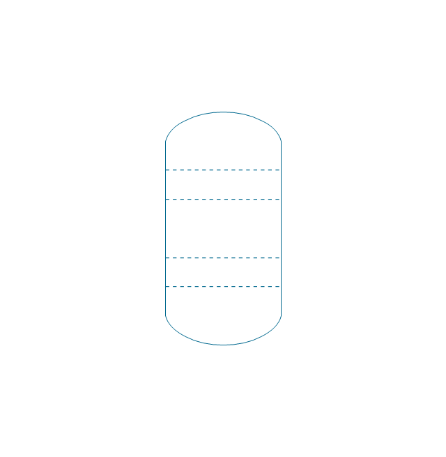
Tray (dashed)
-vessels---vector-stencils-library.png--diagram-flowchart-example.png)
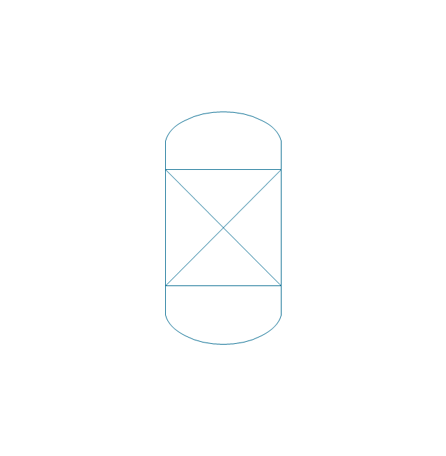
Tray (solid)
-vessels---vector-stencils-library.png--diagram-flowchart-example.png)
Water surface

Branch fitting

Access point

Flanged access point

Vessel flat ends

Vessel curved ends

Vessel angled ends

Column
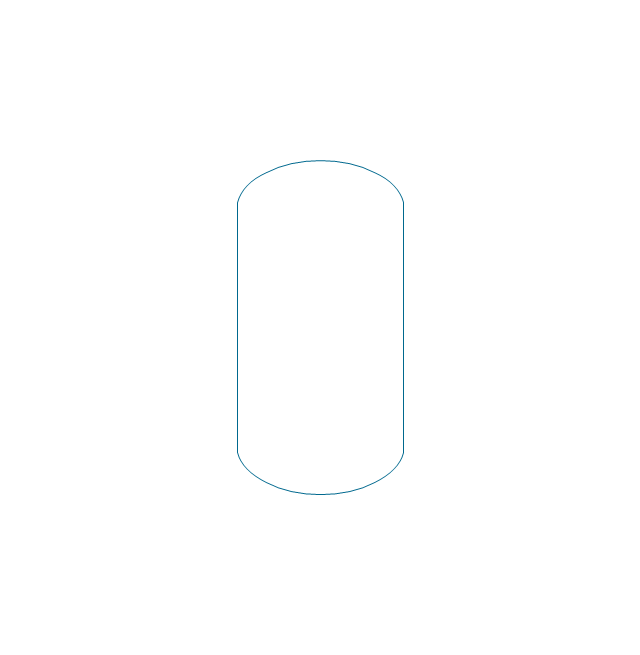
Column (seam)
-vessels---vector-stencils-library.png--diagram-flowchart-example.png)
Tray column
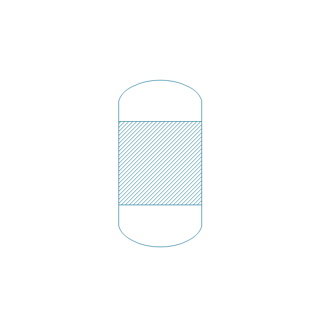
Fluid contacting
Reaction vessel
Open tank with lip

Open tank

Clarifier
Closed tank

Closed tank (peaked roof)
-vessels---vector-stencils-library.png--diagram-flowchart-example.png)
Closed tank (sump)
-vessels---vector-stencils-library.png--diagram-flowchart-example.png)
Closed tank (sump, peaked roof)
-vessels---vector-stencils-library.png--diagram-flowchart-example.png)
Covered tank fixed roof

Covered tank floating roof
Covered tank fixed roof (sump)
-vessels---vector-stencils-library.png--diagram-flowchart-example.png)
Covered tank floating roof (sump)
-vessels---vector-stencils-library.png--diagram-flowchart-example.png)
Gas holder
Storage sphere
Barrel
Gas cylinder

Bag
Carrying vessel moveable

Carrying vessel

Carrying vessel cargo
Autoclave anchor
Autoclave helical
Autoclave propeller
Autoclave anchor (motor)
-vessels---vector-stencils-library.png--diagram-flowchart-example.png)
Autoclave helical (motor)
-vessels---vector-stencils-library.png--diagram-flowchart-example.png)
Autoclave propeller (motor)
-vessels---vector-stencils-library.png--diagram-flowchart-example.png)
Tank
- Symbol Thermostatic Expansion Valve
- Schematic Drawing For Hvac
- Schematic Symbols Of Valves
- Piping Valve Drawing Symbols Pdf
- Block Diagrams | Create Block Diagram | Design elements - HVAC ...
- Hvac Schematic
- Valve Drawing Software
- Design elements - Valves | Plumbing and Piping Plans | Building ...
- Design elements - Pipes (part 1) | Design elements - Valves and ...
- Mechanical Engineering | Engineering | Visio Schematic Hydraulic ...
- Electrical Symbols — Terminals and Connectors | Interior Design ...
- Mechanical Drawing Software | Mechanical Drawing Symbols ...
- Hydraulic Valve Symbols Pdf
- Hydraulic Schematic Symbols Pressure Return
- Design elements - Valve assembly | How To use House Electrical ...
- Mechanical Engineering | Mechanical Design Software | Electrical ...
- Fitness Plans | Electrical Symbols , Electrical Schematic Symbols ...
- Valve Symbols
- Design elements - Valves and fittings | Design elements - Pipes (part ...
- Mechanical Drawing Software | Mechanical Drawing Symbols ...