Electrical Symbols, Electrical Diagram Symbols

Electrical Symbols — Transformers and Windings
Electrical Diagram

The vector stenvils library "Outlets" contains 57 symbols of electrical outlets for drawing building interior design, electrical floor plans and layouts of AC power plugs and sockets.
"AC power plugs and sockets are devices that allow electrically operated equipment to be connected to the primary alternating current (AC) power supply in a building. Electrical plugs and sockets differ in voltage and current rating, shape, size and type of connectors. The types used in each country are set by national standards, some of which are listed in the IEC technical report TR 60083, Plugs and socket-outlets for domestic and similar general use standardized in member countries of IEC.
Plugs and sockets for portable appliances started becoming available in the 1880s, to replace connections to light sockets with easier to use wall-mounted outlets. A proliferation of types developed to address the issues of convenience and protection from electric shock. Today there are approximately 20 types in common use around the world, and many obsolete socket types are still found in older buildings. Co-ordination of technical standards has allowed some types of plugs to be used over wide regions to facilitate trade in electrical appliances, and for the convenience of travellers and consumers of imported electrical goods. Some multi-standard sockets allow use of several different types of plugs; improvised or unapproved adapters between incompatible sockets and plugs may not provide the full safety and performance of an approved adapter." [AC power plugs and sockets. Wikipedia]
The example "Design elements - Outlets" was created using the ConceptDraw PRO diagramming and vector drawing software extended with the Electric and Telecom Plans solution from the Building plans area of ConceptDraw Solution Park.
Electrical outlet symbols

The vector stencils library "Switches and relays" contains 58 symbols of electrical contacts, switches, relays, circuit breakers, selectors, connectors, disconnect devices, switching circuits, current regulators, and thermostats for electrical devices.
"In electrical engineering, a switch is an electrical component that can break an electrical circuit, interrupting the current or diverting it from one conductor to another.
The most familiar form of switch is a manually operated electromechanical device with one or more sets of electrical contacts, which are connected to external circuits. Each set of contacts can be in one of two states: either "closed" meaning the contacts are touching and electricity can flow between them, or "open", meaning the contacts are separated and the switch is nonconducting. The mechanism actuating the transition between these two states (open or closed) can be either a "toggle" (flip switch for continuous "on" or "off") or "momentary" (push-for "on" or push-for "off") type.
A switch may be directly manipulated by a human as a control signal to a system, such as a computer keyboard button, or to control power flow in a circuit, such as a light switch. Automatically operated switches can be used to control the motions of machines, for example, to indicate that a garage door has reached its full open position or that a machine tool is in a position to accept another workpiece. Switches may be operated by process variables such as pressure, temperature, flow, current, voltage, and force, acting as sensors in a process and used to automatically control a system. ... A switch that is operated by another electrical circuit is called a relay. Large switches may be remotely operated by a motor drive mechanism. Some switches are used to isolate electric power from a system, providing a visible point of isolation that can be padlocked if necessary to prevent accidental operation of a machine during maintenance, or to prevent electric shock." [Switch. Wikipedia]
"A relay is an electrically operated switch. Many relays use an electromagnet to mechanically operate a switch, but other operating principles are also used, such as solid-state relays. Relays are used where it is necessary to control a circuit by a low-power signal (with complete electrical isolation between control and controlled circuits), or where several circuits must be controlled by one signal. The first relays were used in long distance telegraph circuits as amplifiers: they repeated the signal coming in from one circuit and re-transmitted it on another circuit. Relays were used extensively in telephone exchanges and early computers to perform logical operations.
A type of relay that can handle the high power required to directly control an electric motor or other loads is called a contactor. Solid-state relays control power circuits with no moving parts, instead using a semiconductor device to perform switching. Relays with calibrated operating characteristics and sometimes multiple operating coils are used to protect electrical circuits from overload or faults; in modern electric power systems these functions are performed by digital instruments still called "protective relays"." [Relay. Wikipedia]
The shapes example "Design elements - Switches and relays" was drawn using the ConceptDraw PRO diagramming and vector drawing software extended with the Electrical Engineering solution from the Engineering area of ConceptDraw Solution Park.
Switch and relay symbols

The vector stencils library "Transformers and windings" contains 29 element symbols of transformers, windings, couplers, metering devices, transductors, magnetic cores, chokes, and a variometer.
Use it to design the electromechanical device schematics and electronic circuit diagrams in the ConceptDraw PRO diagramming and vector drawing software extended with the Electrical Engineering solution from the Engineering area of ConceptDraw Solution Park.
www.conceptdraw.com/ solution-park/ engineering-electrical
Coaxial choke

Transductor

Saturating transformer

1-phase induction voltage regulator

Triplex induction voltage regulator

Induction voltage regulator

Current transformer 2

Current transformer 3

Potential transformer 2

Potential transformer with 3 windings

Outdoor metering device

Linear coupler

Magnetic core, 1 line

Magnetic core, 2 lines

Choke

Variometer

Air-core transformer

Magnetic-core transformer

Air-core transformer, 1 winding adjustable

Magnetic-core transformer, 1 winding adjustable

Air-core transformer, 2 windings adjustable

Magnetic-core transformer, 2 windings adjustable

Air-core transformer, mutual inductor

Magnetic-core transformer, mutual inductor

Transformer 2

Adjustable transformer, 1 winding

Adjustable transformer, mutual inductor

Current transformer 1

Potential transformer

The vector stencils library Alarm and access control contains 80 symbols of digital proximity equipment, locking hardware, and access control equipment.
"An alarm device or system of alarm devices gives an audible, visual or other form of alarm signal about a problem or condition. Alarm devices are often outfitted with a siren." [Alarm device. Wikipedia]
"An access control point, which can be a door, turnstile, parking gate, elevator, or other physical barrier, where granting access can be electronically controlled. Typically, the access point is a door. An electronic access control door can contain several elements. At its most basic, there is a stand-alone electric lock. The lock is unlocked by an operator with a switch. To automate this, operator intervention is replaced by a reader. The reader could be a keypad where a code is entered, it could be a card reader, or it could be a biometric reader. Readers do not usually make an access decision, but send a card number to an access control panel that verifies the number against an access list. To monitor the door position a magnetic door switch can be used. In concept, the door switch is not unlike those on refrigerators or car doors. Generally only entry is controlled, and exit is uncontrolled. In cases where exit is also controlled, a second reader is used on the opposite side of the door. In cases where exit is not controlled, free exit, a device called a request-to-exit (REX) is used. Request-to-exit devices can be a push-button or a motion detector. When the button is pushed, or the motion detector detects motion at the door, the door alarm is temporarily ignored while the door is opened. Exiting a door without having to electrically unlock the door is called mechanical free egress. This is an important safety feature. In cases where the lock must be electrically unlocked on exit, the request-to-exit device also unlocks the door." [Access control. Wikipedia]
Use the design elements library Alarm and access control for drawing layout floor plans, blueprints, and wiring diagrams of intrusion systems, time and attendance systems, card and code access control security systems, internal and external security control systems using the ConceptDraw PRO diagramming and vector drawing software.
The shapes library Alarm and access control is included in the Security and Access Plans solution from the Building Plans area of ConceptDraw Solution Park.
Alarm and access control symbols

Electrical Engineering

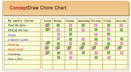
Chore charts with ConceptDraw DIAGRAM
Electrical Design Software

Residential Electric Plan

Network Visualization with ConceptDraw DIAGRAM
- Electrical Symbols , Electrical Diagram Symbols | Circuit Digrom Of ...
- Electrical Symbols , Electrical Diagram Symbols | Electrical Drawing ...
- Electrical Symbols , Electrical Diagram Symbols | Electrical Symbols ...
- Electrical Symbols , Electrical Diagram Symbols | Flow Chart For ...
- What Symbol Of Electric Chock Coil
- Electrical Symbols , Electrical Diagram Symbols | Electrical Symbols ...
- Iron Core Inductor Choke Circuit Diagram
- Electrical Symbols — Transformers and Windings | Transformers ...
- Electrical Symbols , Electrical Diagram Symbols | How To use House ...
- Electrical Symbols — Transformers and Windings | Electrical ...
- Electrical Symbols , Electrical Diagram Symbols | Electrical Symbols ...
- Electrical Symbols — Switches and Relays | Cisco Switches and ...
- Design elements - Alarm and access control | Electric Shock ...
- Electrical Drawing Software and Electrical Symbols | Electrical ...
- Electrical Symbols — Transformers and Windings | Electrical ...
- Electrical Drawing Software and Electrical Symbols | Electrical ...
- Electrical Symbols , Electrical Diagram Symbols | Electrical Drawing ...
- Electrical Symbols , Electrical Diagram Symbols | How To use House ...
- Electrical Symbols — Transformers and Windings | Design elements ...
- Electrical Symbols — Transformers and Windings | Electrical ...