Local area network (LAN). Computer and Network Examples
. Computer and Network Examples")

"A computer network diagram is a schematic depicting the nodes and connections amongst nodes in a computer network or, more generally, any telecommunications network. ...
Depending on whether the diagram is intended for formal or informal use, certain details may be lacking and must be determined from context. ...
At different scales diagrams may represent various levels of network granularity. At the LAN level, individual nodes may represent individual physical devices, such as hubs or file servers, while at the WAN level, individual nodes may represent entire cities. In addition, when the scope of a diagram crosses the common LAN/ MAN/ WAN boundaries, representative hypothetical devices may be depicted instead of showing all actually existing nodes." [Computer network diagram. Wikipedia]
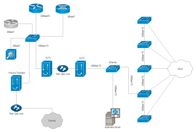
The Cisco computer network diagram example "Network organization chart" was created using the ConceptDraw PRO diagramming and vector drawing software extended with the Cisco Network Diagrams solution from the Computer and Networks area of ConceptDraw Solution Park.
Depending on whether the diagram is intended for formal or informal use, certain details may be lacking and must be determined from context. ...
At different scales diagrams may represent various levels of network granularity. At the LAN level, individual nodes may represent individual physical devices, such as hubs or file servers, while at the WAN level, individual nodes may represent entire cities. In addition, when the scope of a diagram crosses the common LAN/ MAN/ WAN boundaries, representative hypothetical devices may be depicted instead of showing all actually existing nodes." [Computer network diagram. Wikipedia]
The Cisco computer network diagram example "Network organization chart" was created using the ConceptDraw PRO diagramming and vector drawing software extended with the Cisco Network Diagrams solution from the Computer and Networks area of ConceptDraw Solution Park.
Cisco network diagram
Activity Network Diagram Method

Metropolitan area networks (MAN). Computer and Network Examples
. Computer and Network Examples")
Draw Diagram on Mac

Network Diagram Software LAN Network Diagrams & Diagrams for LAN Physical Office Network Diagrams

Visual Presentations Made Easy with Diagramming Software


Network Diagramming Software for Design Cisco Network Diagrams
")
Types of Welding in Flowchart

Cisco Routers. Cisco icons, shapes, stencils and symbols
 Router subdued Router-with-silicon-switch Wavelength-router NetFlow-router uBR910 Broadband-router Gigabit-switch-ATM-tag-router ATM-tag-switch-router Edge-label-switch-router Edge-label-switch-router-with-NetFlow Cisco-7505 Cisco-7507 Cisco-7500-ARS-(7513) Voice-enabled-router TDM-router IP-telephony-router IAD-router Content-service-router Cisco-storage-router Router-with-firewall Wireless-router ASR-1000-series ATM-3800 AXP Cable-modem Ground-terminal. Network equipment refers to hardware devices designed for local area networks, both wired and wireless. Active network equipment is powered from the electricity supply, portable battery, the computer via USB-port and other sources, also it can be used for amplification, conversion and processing of the network signal.")
- Chart On Networking Lan Wan Man Etc
- Network organization chart | Model Based On Lan Man Wan
- Making Project On Chart Lan Wan Man With Diagram
- Computer Chart On Lan Man Wan
- Graph Of Lan Man Wan
- Diagrams Of Lan Wan Man Networks
- Lan Wan Man Chart
- Lan Man Wan Compare In Charte
- Explain Lan Man Wan With Diagrams
- Types Of Networks Lan Wan Man All In One Chart With Diagram