"A bus network is a network topology in which nodes are connected in a daisy chain by a linear sequence of buses. ...
The bus is the data link in a bus network. The bus can only transmit data in one direction, and if any network segment is severed, all network transmission ceases.
A host on a bus network is called a station or workstation. In a bus network, every station receives all network traffic, and the traffic generated by each station has equal transmission priority. Each network segment is, therefore, a collision domain. In order for nodes to transmit on the same cable simultaneously, they use a media access control technology such as carrier sense multiple access (CSMA) or a bus master." [Bus network. Wikipedia]
The bus network topology diagram example was created using the ConceptDraw PRO diagramming and vector drawing software extended with the Computer and Networks solution from the Computer and Networks area of ConceptDraw Solution Park.
Bus topology

Network Diagram Examples


Basic Network Diagram

MS Visio Look a Like Diagrams

"Network topology is the arrangement of the various elements (links, nodes, etc.) of a computer network. Essentially, it is the topological structure of a network, and may be depicted physically or logically. Physical topology refers to the placement of the network's various components, including device location and cable installation, while logical topology shows how data flows within a network, regardless of its physical design. Distances between nodes, physical interconnections, transmission rates, and/ or signal types may differ between two networks, yet their topologies may be identical. The study of network topology recognizes eight basic topologies: Point-to-point, Bus, Star, Ring or circular, Mesh, Tree, Hybrid, Daisy chain." [Network topology. Wikipedia]
The computer network topologies diagram example was created using the ConceptDraw PRO diagramming and vector drawing software extended with the Computer and Networks solution from the Computer and Networks area of ConceptDraw Solution Park.
The computer network topologies diagram example was created using the ConceptDraw PRO diagramming and vector drawing software extended with the Computer and Networks solution from the Computer and Networks area of ConceptDraw Solution Park.
Network topologies

Network Diagramming with ConceptDraw DIAGRAM

 Universal Diagramming Area
This area collects solutions for drawing diagrams, charts, graphs, matrices, geographic and road maps for education, science, engineering, business.
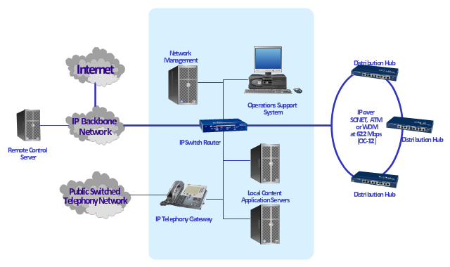
"A cable television headend is a master facility for receiving television signals for processing and distribution over a CATV system. The headend facility is normally unstaffed and surrounded by some type of security fencing and is typically a building or large shed housing electronic equipment used to receive and re-transmit video over the local cable infrastructure. One can also find head ends in power line communication (PLC) substations and Internet communications networks." [Cable television headend. Wikipedia]
This regional cable head-end diagram example was created using the ConceptDraw PRO diagramming and vector drawing software extended with the Computer and Networks solution from the Computer and Networks area of ConceptDraw Solution Park.
This regional cable head-end diagram example was created using the ConceptDraw PRO diagramming and vector drawing software extended with the Computer and Networks solution from the Computer and Networks area of ConceptDraw Solution Park.
Network diagram
 Metro Map
Metro Map solution extends ConceptDraw DIAGRAM software with templates, samples and library of vector stencils for drawing the metro maps, route maps, bus and other transport schemes, or design tube-style infographics.
- Network Diagram Examples | Bus network topology diagram | Basic ...
- Bus network topology diagram
- Bus network topology diagram | Network Diagram Examples ...
- Regional cable head-end diagram | Bus network topology diagram |
- Network Topology | Cisco Network Topology | Bus network topology ...
- Network Topology | Cisco Network Topology | Network Diagram ...
- Network Diagram Examples | Network Configuration | ConceptDraw ...
- Network topologies diagram | Network Diagram Examples | 3D ...
- Network Topology | Network Diagram Examples | Cisco Network ...
- Network Diagram Examples
- Network topologies diagram | Network Topology | Cisco Network ...
- Network Diagram Examples | Computer and Networks | 3D Network ...
- Network Diagram Examples | 3D Network Diagram Software ...
- Network Diagram Examples | Network Diagramming Software for ...
- Network Diagram Examples | Audio and Video Connectors ...
- Network Diagram Examples | Network Configuration | Network ...
- Regional cable head-end diagram | Cisco Network Objects in ...
- Network Hubs | Satellite network diagram | Cisco Network Templates |
- Network Topology | Network Configuration | Basic Network Diagram |
- Network Diagram Examples | Physical LAN and WAN diagram ...