 Floor Plans
Construction, repair and remodeling of the home, flat, office, or any other building or premise begins with the development of detailed building plan and floor plans. Correct and quick visualization of the building ideas is important for further construction of any building.
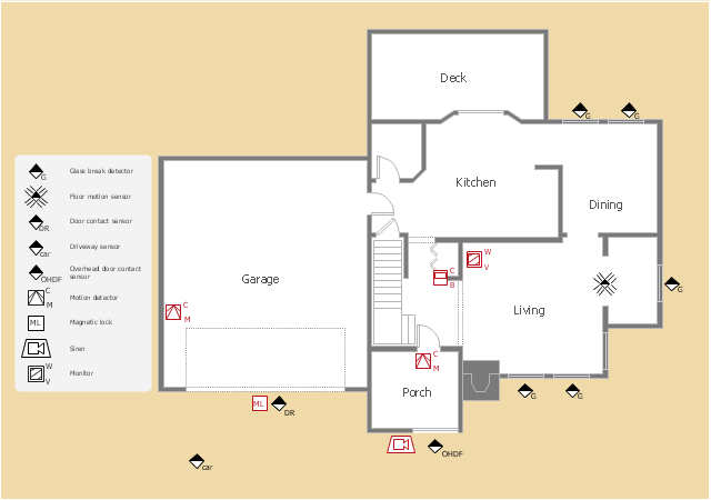
"A security alarm is a system designed to detect intrusion – unauthorized entry – into a building or area. Security alarms are used in residential, commercial, industrial, and military properties for protection against burglary (theft) or property damage, as well as personal protection against intruders. Car alarms likewise protect vehicles and their contents. Prisons also use security systems for control of inmates.
Some alarm systems serve a single purpose of burglary protection; combination systems provide both fire and intrusion protection. Intrusion alarm systems may also be combined with closed-circuit television surveillance systems to automatically record the activities of intruders, and may interface to access control systems for electrically locked doors. Systems range from small, self-contained noisemakers, to complicated, multi-area systems with computer monitoring and control." [Security alarm. Wikipedia]
The example "Security system plan" was created using the ConceptDraw PRO diagramming and vector drawing software extended with the Security and Access Plans solution from the Building Plans area of ConceptDraw Solution Park.
Security system plan
 Infographics Area
Solutions of the area What is Infographics from ConceptDraw Solution Park collect templates, samples and vector stencils libraries with design elements for the drawing information graphics.
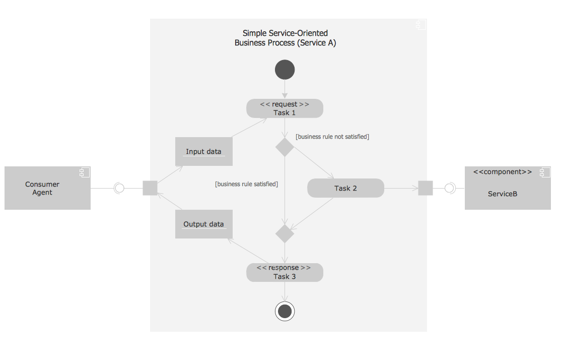
Process with UML
 Workflow Diagrams
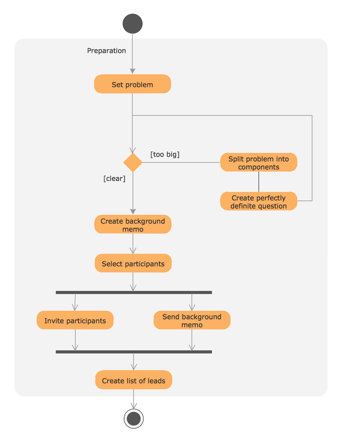
Workflow Diagrams solution extends ConceptDraw DIAGRAM software with samples, templates and vector stencils library for drawing the work process flowcharts.
Diagramming Software for Design UML Collaboration Diagrams


Mesh Network Topology Diagram

UML Process Diagram Example
Entity Relationship Diagram Symbols

 Computer Network Diagrams
Computer Network Diagrams solution extends ConceptDraw DIAGRAM software with samples, templates and libraries of vector icons and objects of computer network devices and network components to help you create professional-looking Computer Network Diagrams, to plan simple home networks and complex computer network configurations for large buildings, to represent their schemes in a comprehensible graphical view, to document computer networks configurations, to depict the interactions between network's components, the used protocols and topologies, to represent physical and logical network structures, to compare visually different topologies and to depict their combinations, to represent in details the network structure with help of schemes, to study and analyze the network configurations, to communicate effectively to engineers, stakeholders and end-users, to track network working and troubleshoot, if necessary.
- Flat design floor plan | One Room Self Contained House Plan
- Building Plan For A Room Self Contained
- Network Topologies | House Plans For A Single Self Contained Room
- Single Room Self Contained Building Plan
- Single Room Self Contained Floor Plan
- Self Contained Single Room House Plans For Single People
- Self Contained Room Plan
- Self Contain Rooms Plan
- A Room Self Contain Sketch
- One Flat And One Self Contain House Plan