ATM Network. Computer and Network Examples


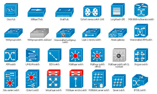
The vector stencils library "Cisco switches and hubs" contains 26 symbols for drawing computer network diagrams using the ConceptDraw PRO diagramming and vector drawing software.
"A network switch (sometimes known as a switching hub) is a computer networking device that is used to connect many devices together on a computer network. A switch is considered more advanced than a hub because a switch will only send a message to the device that needs or requests it, rather than broadcasting the same message out of each of its ports.
A switch is a multi-port network bridge that processes and forwards data at the data link layer (layer 2) of the OSI model. Some switches have additional features, including the ability to route packets. These switches are commonly known as layer-3 or multilayer switches. Switches exist for various types of networks including Fibre Channel, Asynchronous Transfer Mode, InfiniBand, Ethernet and others." [Network switch. Wikipedia]
"An Ethernet hub, active hub, network hub, repeater hub, multiport repeater or hub is a device for connecting multiple Ethernet devices together and making them act as a single network segment. It has multiple input/ output (I/ O) ports, in which a signal introduced at the input of any port appears at the output of every port except the original incoming. A hub works at the physical layer (layer 1) of the OSI model. The device is a form of multiport repeater. Repeater hubs also participate in collision detection, forwarding a jam signal to all ports if it detects a collision.
Some hubs may also come with a BNC and/ or Attachment Unit Interface (AUI) connector to allow connection to legacy 10BASE2 or 10BASE5 network segments." [Ethernet hub. Wikipedia]
The example "Design elements - Cisco switches and hubs" is included in the Cisco Network Diagrams solution from the Computer and Networks area of ConceptDraw Solution Park.
Cisco switches and hubs symbols
Virtual private networks (VPN). Computer and Network Examples

The vector stencils library "Computers and network isometric" contains 56 3D clipart images of computer and network devices and equipment for drawing network diagrams.
The clip art example "Computers and network isometric - Vector stencils library" was created using the ConceptDraw PRO diagramming and vector drawing software extended with the Computer and Networks solution from the Computer and Networks area of ConceptDraw Solution Park.
The clip art example "Computers and network isometric - Vector stencils library" was created using the ConceptDraw PRO diagramming and vector drawing software extended with the Computer and Networks solution from the Computer and Networks area of ConceptDraw Solution Park.
Laptop

DDCS

Server

Webcam

Wireless Network Storage

Personal computer

VoIP phone

Fax

Plotter

Mobile phone

Feature phone

Printer

Satellite dish

Satellite antenna

Automatic-tracking satellite dish
Wireless access point

Wireless router

Router

Network switch

Network device

Mobile GPS Terminal

GPS phone

Television antenna

Radio tower

Base station

Satellite

In-vehicle satellite telecommunication

Satellite dishes on ship

Airplane

Internet

Man

Woman

Call-center

Honeycomb

Mountain

Radio waves

Radio waves

Tower block

Office building

House

House

Globe

Wireless security camera

Truck

Tree

Conifer tree

1U hub / switch

2U hub / switch

1U server

2U Server

3U Server

4U Server

Communications satellite

Car

Radio waves

Firewall

Near field communication (NFC). Computer and Network Examples

Pyramid Diagram
Campus Area Networks (CAN). Computer and Network Examples

Network Glossary Definition

 ATM UML Diagrams
The ATM UML Diagrams solution lets you create ATM solutions and UML examples. Use ConceptDraw DIAGRAM as a UML diagram creator to visualize a banking system.
Cross-Functional Flowchart


- ATM Network. Computer and Network Examples | Network ...
- Asynchronous Transfer Mode Topology In Data Communication And ...
- UML Deployment Diagram Example - ATM System UML diagrams ...
- ATM Network. Computer and Network Examples | ATM UML ...
- Network Layout Floor Plans | What Is Atm Topology In Dcn
- ATM Network. Computer and Network Examples | UML Deployment ...
- ATM UML Diagrams | Computer Network Diagrams | Atm Network ...
- Network Layout Floor Plans | What Are Atm Topology In Dcn
- ATM UML Diagrams | UML Use Case Diagram Example. Services ...
- Projects Diagram Of Atm Management