 ATM UML Diagrams
The ATM UML Diagrams solution lets you create ATM solutions and UML examples. Use ConceptDraw DIAGRAM as a UML diagram creator to visualize a banking system.
ATM Network. Computer and Network Examples


Diagramming software for Amazon Web Service icon set: Monitoring, Deployment, Management
 AWS Architecture Diagrams
AWS Architecture Diagrams with powerful drawing tools and numerous predesigned Amazon icons and AWS simple icons is the best for creation the AWS Architecture Diagrams, describing the use of Amazon Web Services or Amazon Cloud Services, their application for development and implementation the systems running on the AWS infrastructure. The multifarious samples give you the good understanding of AWS platform, its structure, services, resources and features, wide opportunities, advantages and benefits from their use; solution’s templates are essential and helpful when designing, description and implementing the AWS infrastructure-based systems. Use them in technical documentation, advertising and marketing materials, in specifications, presentation slides, whitepapers, datasheets, posters, etc.
HelpDesk
How to Create a Bank ATM Use Case Diagram

Near field communication (NFC). Computer and Network Examples

 Enterprise Architecture Diagrams
Enterprise Architecture Diagrams solution extends ConceptDraw DIAGRAM software with templates, samples and library of vector stencils for drawing the diagrams of enterprise architecture models.
UML Use Case Diagram Example. Services UML Diagram. ATM system

Bank System
Cisco Network Design. Cisco icons, shapes, stencils, symbols and design elements

 Software Development Area
Solutions from the Software Development Area of ConceptDraw Solution Park collect templates, samples and libraries of vector stencils for drawing the software engineering diagrams and user interface design prototypes.
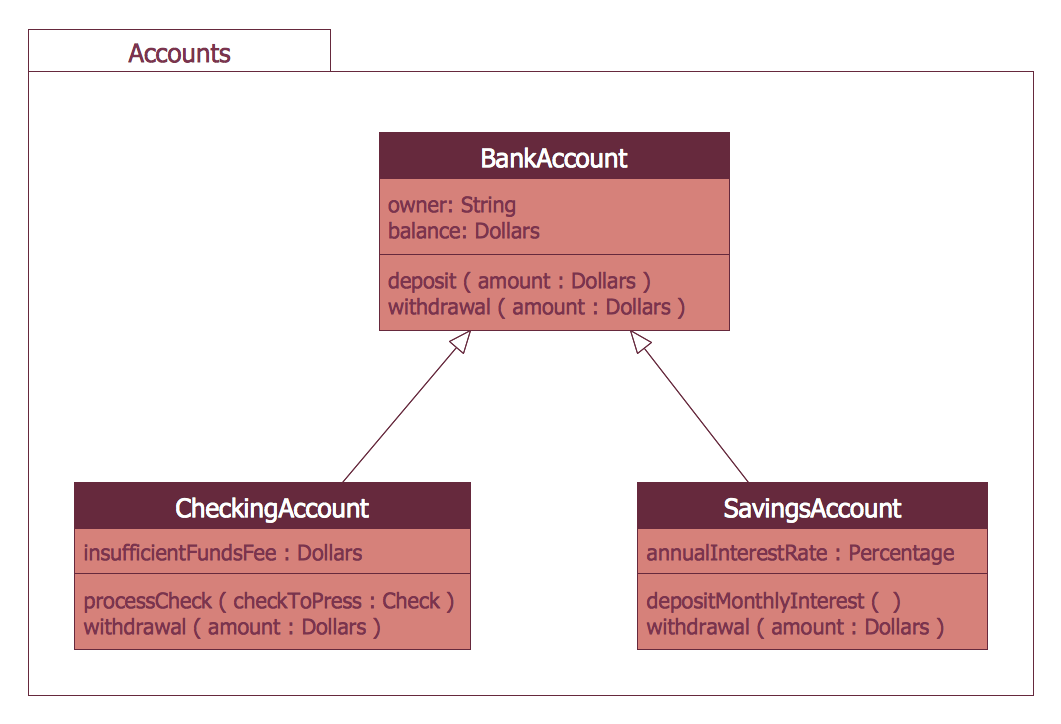
Bank UML Diagram

Network Topologies


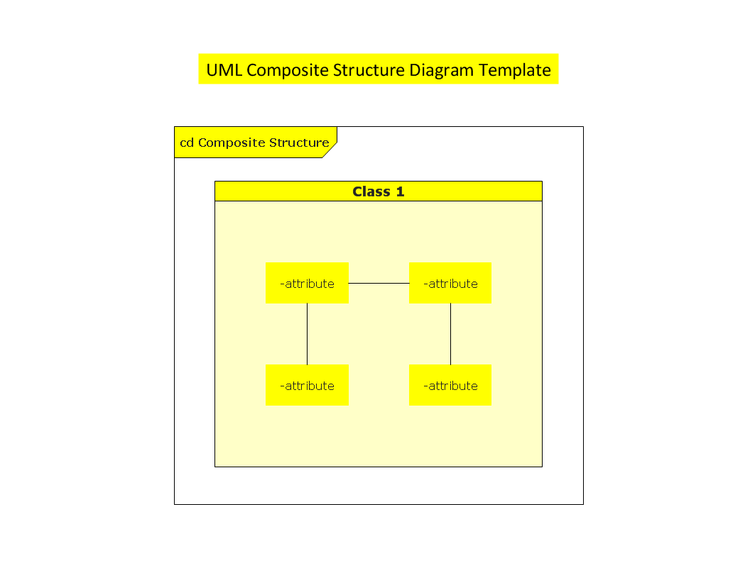
UML Composite Structure Diagram

- Atm Architecture Design Representing An Atm Machine In An
- ATM UML Diagrams | Enterprise Architecture Diagrams | Office ...
- ATM UML Diagrams | UML Package Diagram. Design Elements ...
- Architectural Design For Atm System
- AWS Architecture Diagrams | ATM UML Diagrams | Enterprise ...
- Architectural Plan Of Atm Room
- Enterprise Architecture Diagrams | AWS Architecture Diagrams ...
- ATM UML Diagrams | Office Layout Plans | Floor Plans | Atm Room ...
- Atm Bank Design Layout Plan
- Architecture Design For Bank Atm System
- Atm Architecture Diagram
- AWS Architecture Diagrams | Bank UML Diagram | ATM UML ...
- Enterprise Architecture Diagrams | ATM UML Diagrams | AWS ...
- Design Based Architecture Of Atm
- ATM UML Diagrams | Rail transport - Design elements | Office ...
- ATM UML Diagrams | How to Create a Bank ATM Use Case ...
- Architectural Floor Plan Of An Atm Machine With Pictures
- Rail transport - Design elements | Office Layout Plans | ATM Network ...
- State Machine Diagram | ATM UML Diagrams | UML Use Case ...
- UML Deployment Diagram Example - ATM System UML diagrams ...