The circuit diagram example "Amplifier" was redesigned from the Wikimedia Commons file: Slika br.5.JPG.
[commons.wikimedia.org/ wiki/ File:Slika_ br.5.JPG]
This file is made available under the Creative Commons CC0 1.0 Universal Public Domain Dedication. [creativecommons.org/ publicdomain/ zero/ 1.0/ deed.en]
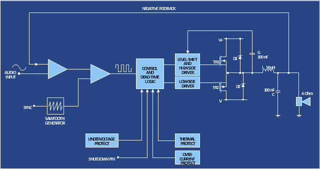
"An electronic amplifier, amplifier, or (informally) amp is an electronic device that increases the power of a signal. It does this by taking energy from a power supply and controlling the output to match the input signal shape but with a larger amplitude. In this sense, an amplifier modulates the output of the power supply.
There are four basic types of electronic amplifier: the voltage amplifier, the current amplifier, the transconductance amplifier, and the transresistance amplifier. A further distinction is whether the output is a linear or nonlinear representation of the input. Amplifiers can also be categorized by their physical placement in the signal chain." [Amplifier. Wikipedia]
The circuit diagram example "Amplifier" was created using the ConceptDraw PRO diagramming and vector drawing software extended with the Electrical Engineering solution from the Engineering area of ConceptDraw Solution Park.
[commons.wikimedia.org/ wiki/ File:Slika_ br.5.JPG]
This file is made available under the Creative Commons CC0 1.0 Universal Public Domain Dedication. [creativecommons.org/ publicdomain/ zero/ 1.0/ deed.en]
"An electronic amplifier, amplifier, or (informally) amp is an electronic device that increases the power of a signal. It does this by taking energy from a power supply and controlling the output to match the input signal shape but with a larger amplitude. In this sense, an amplifier modulates the output of the power supply.
There are four basic types of electronic amplifier: the voltage amplifier, the current amplifier, the transconductance amplifier, and the transresistance amplifier. A further distinction is whether the output is a linear or nonlinear representation of the input. Amplifiers can also be categorized by their physical placement in the signal chain." [Amplifier. Wikipedia]
The circuit diagram example "Amplifier" was created using the ConceptDraw PRO diagramming and vector drawing software extended with the Electrical Engineering solution from the Engineering area of ConceptDraw Solution Park.
Circuit diagram
The circuit diagram example "Amplifier" was redesigned from the Wikimedia Commons file: Slika br.5.JPG.
[commons.wikimedia.org/ wiki/ File:Slika_ br.5.JPG]
This file is made available under the Creative Commons CC0 1.0 Universal Public Domain Dedication. [creativecommons.org/ publicdomain/ zero/ 1.0/ deed.en]
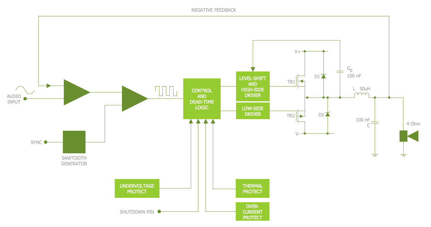
"An electronic amplifier, amplifier, or (informally) amp is an electronic device that increases the power of a signal. It does this by taking energy from a power supply and controlling the output to match the input signal shape but with a larger amplitude. In this sense, an amplifier modulates the output of the power supply.
There are four basic types of electronic amplifier: the voltage amplifier, the current amplifier, the transconductance amplifier, and the transresistance amplifier. A further distinction is whether the output is a linear or nonlinear representation of the input. Amplifiers can also be categorized by their physical placement in the signal chain." [Amplifier. Wikipedia]
The circuit diagram example "Amplifier" was created using the ConceptDraw PRO diagramming and vector drawing software extended with the Electrical Engineering solution from the Engineering area of ConceptDraw Solution Park.
[commons.wikimedia.org/ wiki/ File:Slika_ br.5.JPG]
This file is made available under the Creative Commons CC0 1.0 Universal Public Domain Dedication. [creativecommons.org/ publicdomain/ zero/ 1.0/ deed.en]
"An electronic amplifier, amplifier, or (informally) amp is an electronic device that increases the power of a signal. It does this by taking energy from a power supply and controlling the output to match the input signal shape but with a larger amplitude. In this sense, an amplifier modulates the output of the power supply.
There are four basic types of electronic amplifier: the voltage amplifier, the current amplifier, the transconductance amplifier, and the transresistance amplifier. A further distinction is whether the output is a linear or nonlinear representation of the input. Amplifiers can also be categorized by their physical placement in the signal chain." [Amplifier. Wikipedia]
The circuit diagram example "Amplifier" was created using the ConceptDraw PRO diagramming and vector drawing software extended with the Electrical Engineering solution from the Engineering area of ConceptDraw Solution Park.
Circuit diagram
Electrical Symbols, Electrical Diagram Symbols

Electrical Drawing Software and Electrical Symbols

Electrical Symbols — Logic Gate Diagram

Circuits and Logic Diagram Software

The circuit diagram example "Bipolar current mirror" was redesigned from the Wikipedia file: Current mirror.png.
[en.wikipedia.org/ wiki/ File:Current_ mirror.png]
This file is licensed under the Creative Commons Attribution-Share Alike 3.0 Unported license. [creativecommons.org/ licenses/ by-sa/ 3.0/ deed.en]
"A current mirror is a circuit designed to copy a current through one active device by controlling the current in another active device of a circuit, keeping the output current constant regardless of loading. The current being 'copied' can be, and sometimes is, a varying signal current. Conceptually, an ideal current mirror is simply an ideal inverting current amplifier that reverses the current direction as well or it is a current-controlled current source (CCCS). The current mirror is used to provide bias currents and active loads to circuits. ...
Basic BJT current mirror.
If a voltage is applied to the BJT base-emitter junction as an input quantity and the collector current is taken as an output quantity, the transistor will act as an exponential voltage-to-current converter. By applying a negative feedback (simply joining the base and collector) the transistor can be "reversed" and it will begin acting as the opposite logarithmic current-to-voltage converter; now it will adjust the "output" base-emitter voltage so as to pass the applied "input" collector current.
The simplest bipolar current mirror ... implements this idea. It consists of two cascaded transistor stages acting accordingly as a reversed and direct voltage-to-current converters." [Current mirror. Wikipedia]
The circuit diagram example "Bipolar current mirror" was created using the ConceptDraw PRO diagramming and vector drawing software extended with the Electrical Engineering solution from the Engineering area of ConceptDraw Solution Park.
Circuit diagram

 Electrical Engineering
This solution extends ConceptDraw DIAGRAM.9.5 (or later) with electrical engineering samples, electrical schematic symbols, electrical diagram symbols, templates and libraries of design elements, to help you design electrical schematics, digital and analog
Electrical Symbols, Electrical Schematic Symbols

How To use Electrical and Telecom Plan Software


Electrical Diagram Software


Electrical Design Software

Electrical Symbols — Composite Assemblies

Wiring Diagrams with ConceptDraw DIAGRAM

Electrical Schematic
- American Home Theater Amplifier Circuit Diagram And Layout
- Electrical Symbols, Electrical Diagram Symbols | Circuits and Logic ...
- Amplifier - Circuit diagram | Video and audio - Vector stencils library ...
- Amplifier - Circuit diagram | Simple switched supply - Circuit diagram ...
- Amplifier - Circuit diagram
- Power Full Home Theater Amplifier Circuit Diagram
- Amplifier - Circuit diagram | Electrical Drawing Software and ...
- Amplifier - Circuit diagram | Electrical Symbols — Logic Gate ...
- Amplifier - Circuit diagram | Design elements - Composite ...
- Amplifier - Circuit diagram
- Circuits And Diagrams Of Amplifiers
- Home Theater Amplifier Circuit Diagram
- Amplifier - Circuit diagram | Bipolar current mirror - Circuit diagram ...
- Amplifier - Circuit diagram | Electrical Drawing Software and ...
- Probability Quality Control Tools | Amplifier - Circuit diagram ...
- Amplifier Circuit Schematics
- Bipolar current mirror - Circuit diagram | Amplifier - Circuit diagram ...
- Catv Amplifier Circuit Diagram
- Circuit diagram - EL 34 schematics | Se Amplifier El34 Schematic
- Bipolar current mirror - Circuit diagram | Amplifier - Circuit diagram ...