Basic Flowchart Symbols and Meaning


Physics Symbols

Electrical Symbols, Electrical Diagram Symbols

Data Flow Diagram Symbols. DFD Library

Venn Diagram Examples for Problem Solving. Computer Science. Chomsky Hierarchy

Process Flowchart Symbols

Diagram Flow Chart
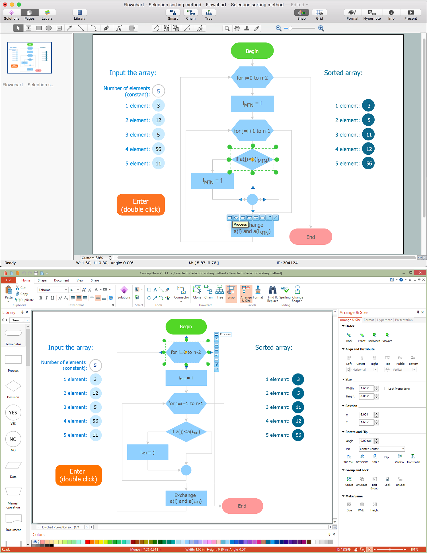
Flow Chart Symbols

 EXPRESS-G data Modeling Diagram
EXPRESS-G data Modeling Diagram solution extends the ConceptDraw DIAGRAM software functionality with capabilities of EXPRESS data modeling language, includes powerful data modeling tools, Express-G diagram tool, database diagram tool, database design tool, wide variety of pre-made vector objects of EXPRESS-G notation and EXPRESS-G diagrams samples allowing software developers, software designers, software engineers and other stakeholders to make their data models for information systems, to develop the databases, to learn the principles of construction EXPRESS-G diagrams and helping to draw their own EXPRESS-G Data Modeling Diagrams, Express-G Diagrams or Database Model Diagram without any efforts.
Components of ER Diagram

- Physics Symbols | Symble Of Physic With Name Images
- Basic Flowchart Symbols and Meaning | Mathematics | Mathematics ...
- Mathematics All Symbol With Name Pic
- Mathematics | Maths Chemistry Physics All Symbol Download
- Physics Symbols | Physics Diagrams | Mathematics Symbols | All ...
- Physics Symbols | Physics Diagrams | Mathematics Symbols ...
- How to Draw Physics Diagrams in ConceptDraw PRO | Physicspdf ...
- Chemistry | Mathematics | Physics All Symbols With Formulas Pdf ...
- Physics Math Symbol Name List
- Maths Physics Chemistry All Symbol Details