Home Automation
Home automation is the automatic control of electronic devices and appliances within a home. It includes all automation mechanisms used for a home, combines hardware and software via a wireless network to control and monitor almost all home attributes like lighting, climate, appliances, home electronics, alarm systems, entertainment systems directly or remotely when you're not at home. Most home automation devices have sensors to track changes in various characteristics (temperature, motion, light, etc.) and are connected to the Internet through different communication protocols. Being installed in a home, the automation system transforms it into a smart home.
In common, the controlled devices are connected to a central smart home hub called a gateway. The user interface allows controlling a gateway and all home automation system at the place or remotely from mobile phone applications, tablets, desktop computers, wall-mounted terminals, or a Web interface through the Internet. The control via voice assistant is also used at the place.
Home automation has a high potential for ensuring comfort, providing security, energy saving, sharing data between family members, and many more. It helps to make our life easier, safer, more convenient and is also an effective tool to manage power consumption and make a home more energy efficient. Home automation helps to switch off lights and appliances, stop heating or cooling automatically according to the schedule. For example, the automatic outdoor switching light on is desired when it gets dark outside and vice versa switching off in the early morning. The automatic decreasing temperature is rational when you are not at home or at night time, it is a cost-effective way to put your heating system or A/C up to turn about an hour before you return home, etc.
Home automation includes monitoring, control, and automation processes. It is used for a variety of goals, to manage the work of lights, appliances, doors, blinds, garage gates, home robots, control temperature, heating, ventilation and air conditioning, water systems, and energy savers. The remote control in real-time via mobile application or voice assistant is a feature of home automation systems. In this way, no matter whether are you at home or not, the home automation system organizes the smart work of your home according to the set schedules and routines, and you just control it.
Modern home automation systems provide the possibility of remote control of all home energy monitors. The use of different smart sensors and control systems makes possible even the accounting of peoples' presence in the home. Home automation supposes the integration of efficient and intelligent energy-saving techniques, information and communication technologies, and renewable energy systems that have a positive environmental impact and decrease electricity costs. For example, it allows the automatic integration of solar panels' energy in the daytime when solar activity is high. Home automation systems also can take decisions about storing or expanding energy.
The operation of the security system is often connected to a home automation system. Home automation can include a variety of smart security system devices and surveillance setups for safety and security. It includes the remote surveillance of security cameras, monitoring of the motion sensors and glass-breaking sensors, central locking, etc.
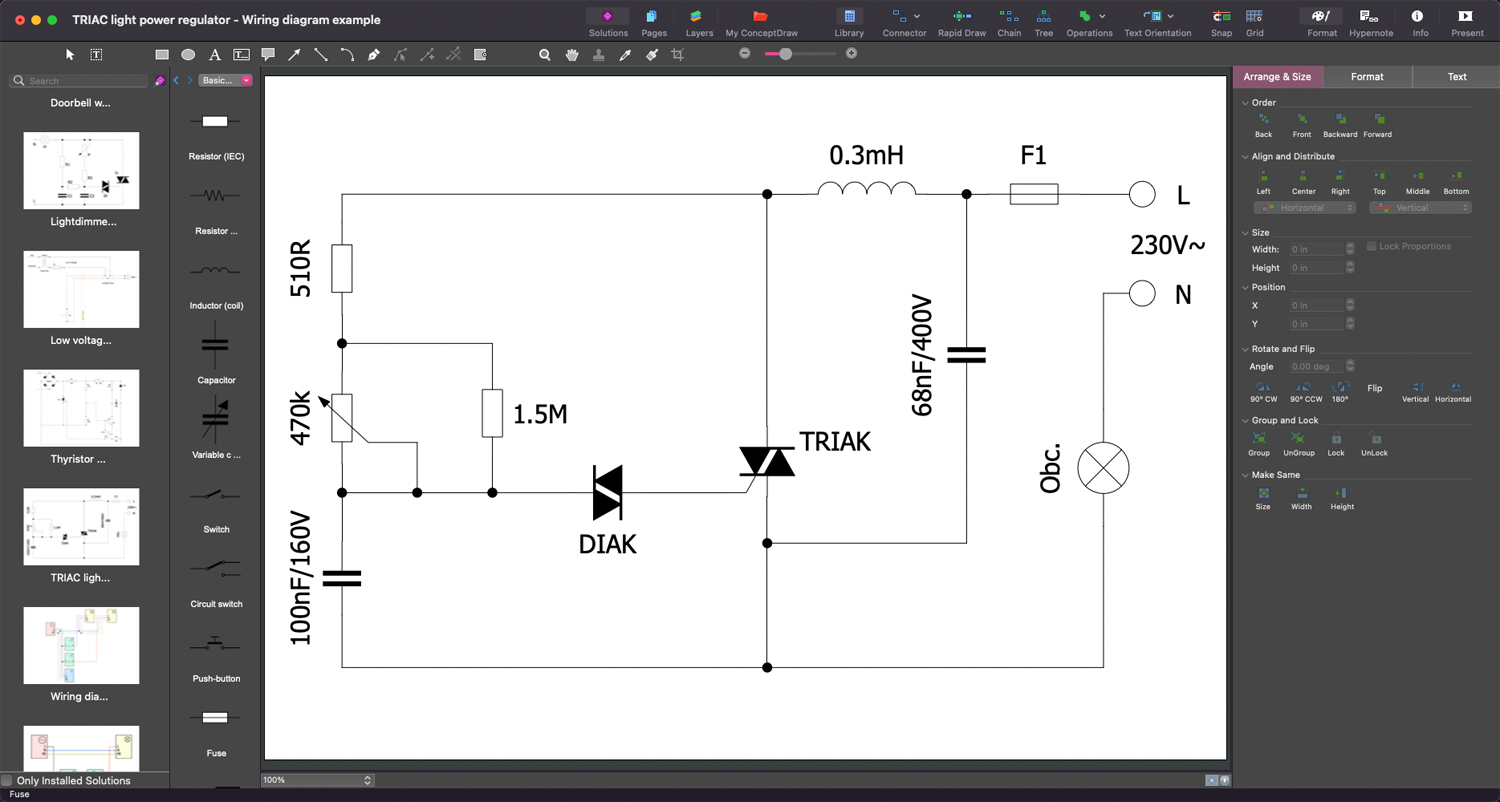
Example 1. Home Automation Plans in ConceptDraw DIAGRAM
The most popular components and devices for home automation systems include:
- sensors for automatic turning lighting on/off by time, scheduling lighting inside and outside your home (to illuminate the plot, paths, porch, gazebo, etc.);
- motion sensors, which automatically realize certain actions as a response to the motion, like lighting upstairs or other places when approaching them, alarming as a part of the signalization system, etc.; smart light switches;
- smart bulbs and smart lights that consume less energy and last several times longer than regular ones, and allow using a smartphone to change lighting characteristics like intensity, brightness, color, turn lighting on/off;
- smart outlets allowing managing lighting without changing your bulbs on the smart ones, easily integrating your older lights or appliances into a new automation system;
- smart thermostats and sensors for climate and effective heating with saving energy, time, and money, allowing you to program the heating and air conditioning systems in a useful schedule, maintain the temperature at a certain value, use less energy when you aren't at home, in the night when you’re sleeping, or in any other way;
- entry sensors for doors and windows and glass break sensors used for the home security system to alert the alarm company in the event of breaking security;
- video surveillance systems;
- water leak sensors, moisture sensors, flood sensors to alarm about a leak and stop it from turning into a flood; being connected to other smart devices, they can even send them an alert to automatically shut off the water;
- devices for motorized control of blinds, curtains, shades, sofas, armchairs, and other details in your home;
- programming appliances to automatically switch them on/off at a certain time, for example, air conditioners, coffee machines, ovens, etc;
- smart kitchen devices;
- robotics including robot vacuums, pool cleaners, and window washers used to automatically clean your home;
- smoke and carbon monoxide detectors that help to prevent danger and alarm when smoke or an increased level of carbon monoxide is detected in the air;
- air quality control sensors, air quality and pollution level monitoring systems; motorized valves;
- home automation devices using voice control;
- smart speakers and voice control devices for voice activating and controlling lights and appliances, playing music, making phone calls, checking the weather, listening to the news, etc;
- baby monitors to help in baby care and protection;
- indoor positioning systems;
- smart garage door openers;
- irrigation and sprinkler control systems, which are cost-efficient in connection with outdoor moisture sensors and help your system to know when it is required to water a garden;
- home automation systems for disabled and elderly;
- pet smart care devices including food dispensers feeding your pets according to the schedule, scheduling locking and unlocking the pet door, sensors to track the presence of a pet in the house, etc.;
- pool sensors allowing adjusting the pool lighting and automatically managing the pH level.
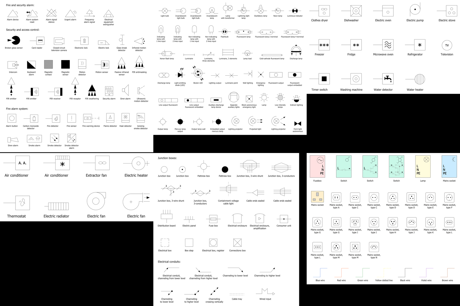
Example 2. Home Automation and Wiring Libraries Design Elements
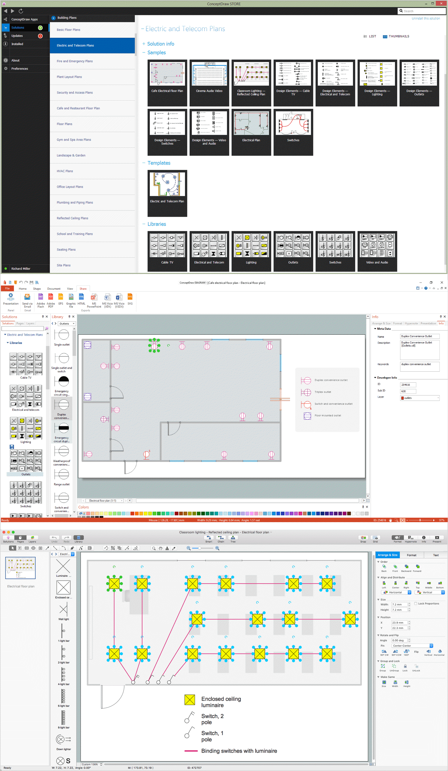
ConceptDraw DIAGRAM software with Home Automation and Wiring solution helps to create plans for smart home automation systems for any building in a few minutes. It includes a collection of samples and 9 libraries with vector design elements to create the Home Automation schematics fast, easily, and professionally.
The solution's libraries include the pictograms and symbols for all elements required for home automation systems including design elements — alarm and security circuits, electric lighting, junction boxes electrical conduits, doorbells and buzzers, and many more. You are free to choose the best smart home devices for your automation system. This solution is efficient to be recommended and chosen as the best automation solution for your home when transforming into a smart home.
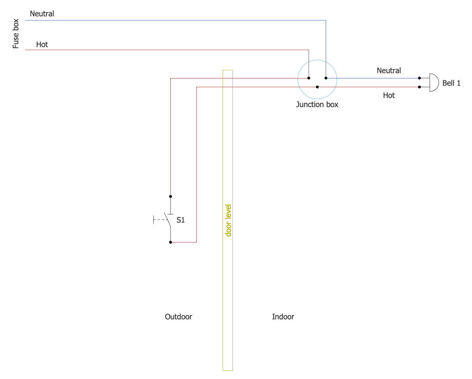
Example 3. Doorbell Wiring Diagram
The Home Automation Diagrams samples you see on this page were created in ConceptDraw DIAGRAM software using the drawing tools of the Home Automation and Wiring Solution. These examples successfully demonstrate the solution's capabilities and the professional results you can achieve using it. An experienced user spent 5-15 minutes creating each of these samples.
Use the drawing tools of the Home Automation and Wiring solution to design your own Home automation diagrams and infographics quick, easy, and effective.
All source documents are vector graphic documents. They are available for reviewing, modifying, or converting to a variety of formats (PDF file, MS PowerPoint, MS Visio, and many other graphic formats) from the ConceptDraw STORE. The Home Automation and Wiring Solution is available for ConceptDraw DIAGRAM users.