Building Plans with ConceptDraw DIAGRAM
Have you decided to build a new house? Or you need to show a planning of an existing house to a potential customer? Probably you need to repair your house? For all these cases you will need the plan of the building.
As a matter of fact, the plan of a building consists of plans of all premises of the building, combined in one document. If the building has several levels or floors, so there can be dozens of such documents. On the building plan all premises of the building with indications of all dimensions (walls, windows, apertures of doors) are presented, also there indicated ventilating shafts and wells, stairs and technical premises.
Building plans are necessary for architects (actually, they are the result of their work), designers, builders, realtors and, surely, to any house owner. Besides, any office building has the plan of emergency evacuation which is also a plan of the building with indication of moving directions at evacuation.
If it is necessary for you to create the building plan you can draw it manually on the sheet of paper, but also you can use special software. With the help of ConceptDraw you can create the building plan of any difficulty. Thanks to special templates and objects libraries this won't take you much time and won't demand special skills.

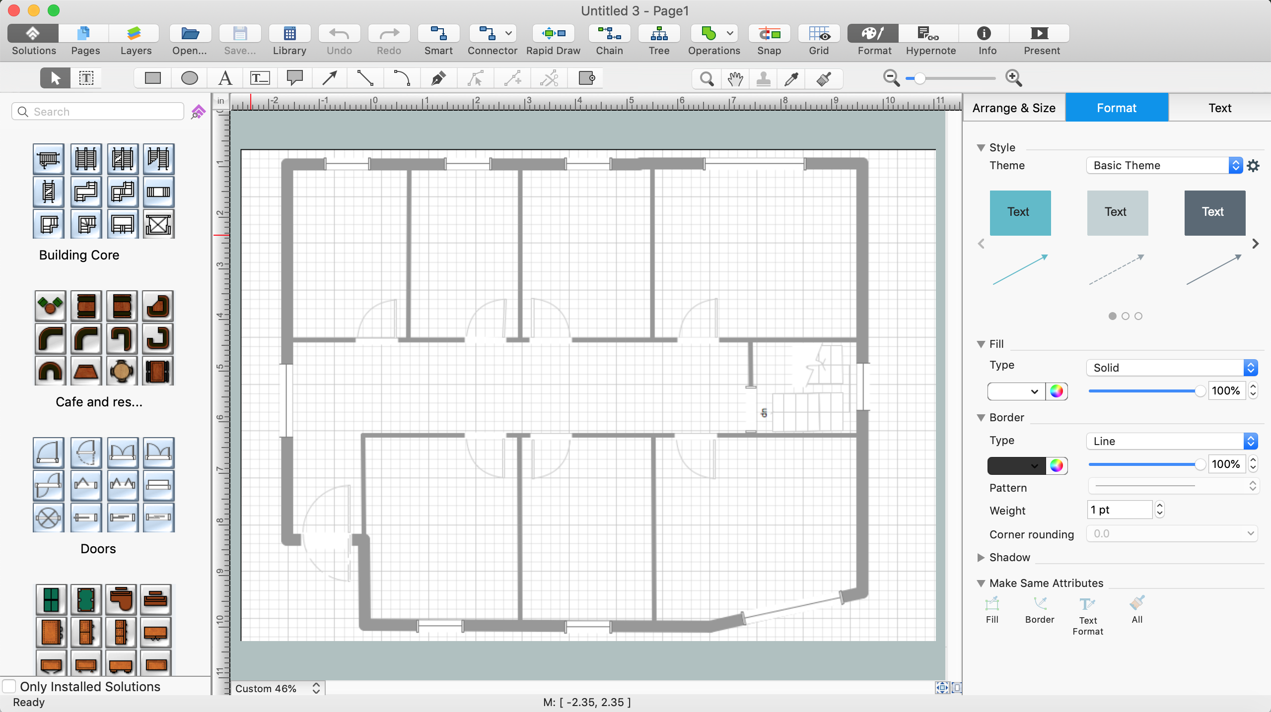
Example 1. Building Plans Solution with ConceptDraw DIAGRAM
As ConceptDraw supports the work with multiple sheet documents, you can keep plans of all building floors in one document not depending on how many floors or levels there exist.

On each sheet your can use unlimited number of layers which is very convenient at creation of the plan of multilevel premises. Besides you can use layers for creation of premises plan with different degree of the detailed elaboration- for example, with furniture or without it. Also the usage of layers is very convenient at the necessity of study of projection of building floors.


Ready building plan can be printed, saved in one of the formats supported by ConceptDraw or send by e-mail to colleagues or clients. Also you can upload ready building plans on your website as the catalogue of proposals.
TEN RELATED HOW TO's:
ConceptDraw will help you to create the room planning of any configuration quickly and skillfully. ConceptDraw contains a number of ready templates for creation of premises plans, and due to libraries with interior objects existing in the program you will be able to place furniture, denote the location of doors and windows and indicate dimensions.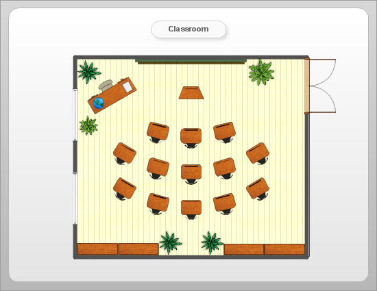
Picture: Room planning with ConceptDraw DIAGRAM
Related Solution:
Sometimes, when it is difficult to create a functional space plan or to rearrange existing one, the art of interior design comes in. It doesn't matter, if you need a cozy bedroom or an office layout plan, you should use appropriate tools to make your design great.
While making a floor plan of a new office it could be useful to apply some design elements such as furniture and office equipment. This diagram presents an office furniture objects that can be used for office interior design planning, or making office furniture and equipment layouts. This vector stencils library is supplied with ConceptDraw Office Layout Plans solution. It contains more then 30 vector objects of office interior for making office floor plans including an office space layout plans and furniture arrangement.
Picture: Interior Design. Office Layout Plan Design Element
Related Solution:
Computer-aided design (CAD) is the use of the computer software to create drawings. Today the large quantity of the technical drawings and architectural designs is created using the CAD software. CAD software makes the design process convenient, efficient and productive.
ConceptDraw DIAGRAM diagramming and vector drawing software allows you the possibility to draw your architectural designs quick, simple and effective.
Use the libraries with a set of vector objects, templates and samples from the Floor Plans Solution from the Building Plans area of ConceptDraw Solution Park for designing your professional architectural designs.
Picture: CAD Software for Architectural Designs
Related Solution:
Still doubting about the number of tables in your cafe? You should create a cafe floor plan that will answer all your questions and reflect all the details of your cafe interior. Get started in several minutes and unlock your creativity with dozens of ConceptDraw DIAGRAM templates and examples!
Dealing with interiors plans for HoReCa business, for example, developing a plan for cafe you will meet with both creative and architectural challenges. First of all , the layout of cafe should be beautiful and convenient for visitors. Being developed sagely a plan of your cafe leads to successful sales and good benefits. Designing a cafe floor plan includes various elements that can be picked out using ConceptDraw Cafe and Restaurant Floor Plan solution. The vector objects library supplied with Cafe and Restaurant solution provides a number of graphic objects for displaying different layouts and styles of catering establishments.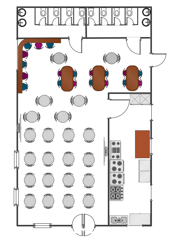
Picture: Cafe Floor Plan. Cafe Floor Plan Examples
Related Solution:
The Building Plans are very useful and even necessary for architects, builders, designers and simple for those who want to build the home, office, flat or anyone other building. They are also convenient for those who want to design or redesign the home, flat, room, etc.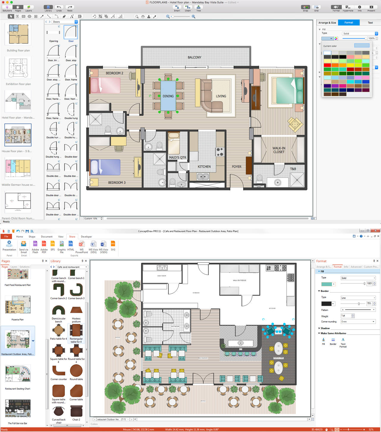
Picture: Building Plan Software. Building Plan Examples
Related Solution:
Living room is the place where all family comes together, where receive guests. The interior of the living room complements the piano which helps to create a warm atmosphere. The piano is not just a musical instrument, in the room interior it becomes the most noticeable detail. The piano always organically entered in any interior.
Best Interior Design Software for Mac OS&Windows ConceptDraw DIAGRAM allows you design the interior of your dreams quick and easy.
Picture: Living Room. Piano in plan
Related Solution:
ConceptDraw DIAGRAM enhanced with Audio, Video, Media solution is a helpful tool for illustration of a CCTV network. It contains library of vector cliparts of video and TV devices and different digital gadgets for drawing such illustrations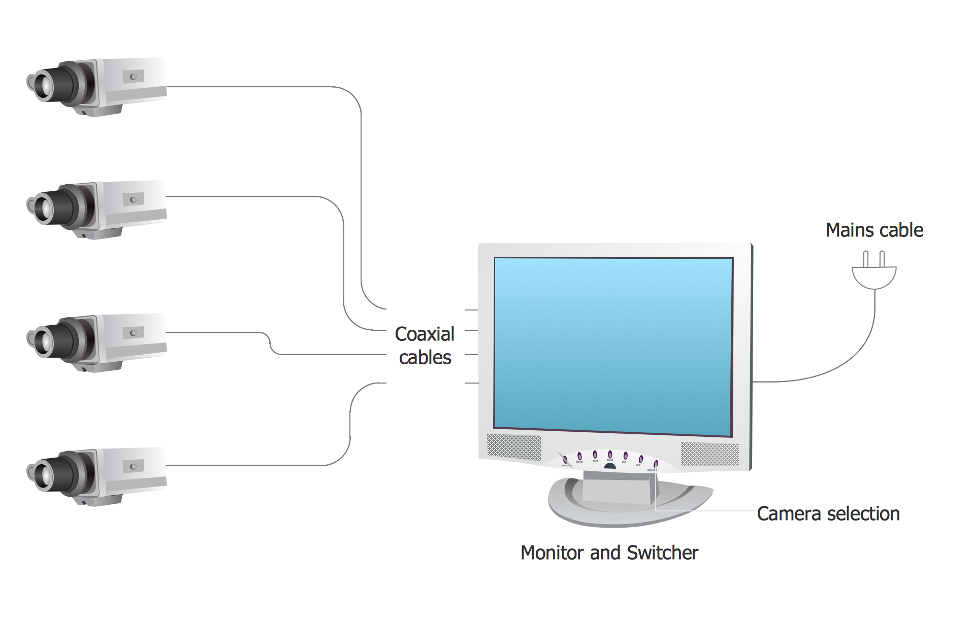
Picture: Basic CCTV System Diagram. CCTV Network Diagram Example
Related Solutions:
A Process Flow Chart is a type of flowchart which is mostly used in industrial, chemical and process engineering for illustrating high-level processes, major plant processes and not shows minor details.
ConceptDraw DIAGRAM diagramming and vector drawing software extended with Flowcharts Solution from the Diagrams Area of ConceptDraw Solution Park is the best way to create Process Flow Chart and other types of flowcharts.
Picture: Process Flow Chart
Related Solution:
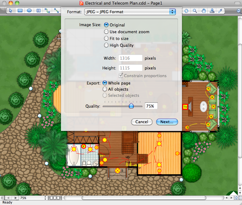
A circuit diagram is sometimes also called an elementary diagram, electronic schematic or electrical diagram circuits. It is essential in construction of any electronic equipment. Among many digital drawing tools available, ConceptDraw DIAGRAM is a leading circuits and logic diagram software, affording for easy and quick creation of even the most advanced and complex diagram designs. This makes it a perfect choice for computer science and any kind of electronic engineering.
This drawing includes the graphic symbols that may be in use while creating a logic circuit diagram. The diagrams of such kind are used in the electronics industry. The logic symbol depicts a device that realizes a Boolean type functions. Practically a logic symbol means transistor, diodes, relays, and other mechanical or optical details which provide function of closing or opening "gates". Totally the logic circuits can involve millions of gates. ConceptDraw Electrical Engineering solution gives the opportunity to create a circuit diagrams both simple and difficult.
Picture: Circuits and Logic Diagram Software
Related Solution:
Unfortunately, a man can’t predict the future and no one is safe from natural disasters, such as floods, earthquakes, hurricanes or fires. Nonetheless, what you can do to ensure safety for you and your relatives is to create an emergency plan, so everyone will know what to do if emergency happens. Keep that plan simple and train it several times a year so that no one could forget any details of it.
Fire and emergency plans are important to supply people with a visual safety solution. This diagram presents a set of standard symbols used to depict fire safety, emergency, and associated information. Using clear and standard symbols on fire emergency plans provides the coherence of collective actions , helps to avoid embarrassment, and improves communications in an emergent situation. The fire emergency symbols are intended for the general emergency and fire service, as well as for building plans ,engineering drawings and insurance diagrams. They can be used during fire extinguishing and evacuation operations, as well as trainings. It includes vector symbols for emergency management mapping, emergency evacuation diagrams and plans.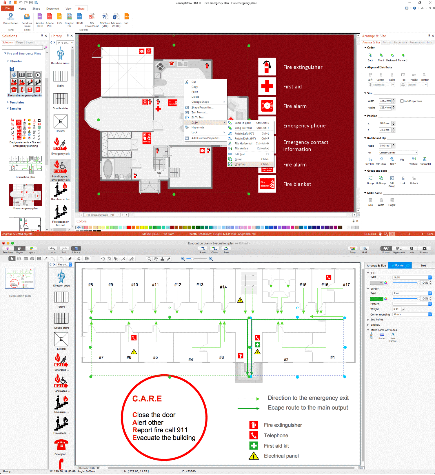
Picture: Emergency Plan
Related Solution: