Samples / Industrial Engineering / Sample Basic Circuit Diagrams
Sample Basic Circuit Diagrams
Sample circuit diagrams in vector graphics format were created using ConceptDraw DIAGRAM diagramming and vector drawing software enhanced with free Basic Circuit Diagrams solution from the Industrial Engineering area.
ConceptDraw DIAGRAM can open and save documents that can be used by Visio (VSD, VDX, and VSDX files) users.
ConceptDraw DIAGRAM allows exporting of vector graphic multipage documents into multiple file formats: vector graphics (SVG, EMF, EPS), bitmap graphics (PNG, JPEG, GIF, BMP, TIFF), web documents (HTML, PDF), PowerPoint presentations (PPT), Adobe Flash (SWF).
Tutorials and Solutions:
Video Guides: Basic Circuit Diagrams
Solutions: Basic Circuit Diagrams for ConceptDraw DIAGRAM
Sample 1: Absorption Frequency Meter
Basic Circuit Diagram sample: This sample shows an absorption frequency meter circuit. This is an electronic instrument applied to measure the frequency of radio waves, to check the output frequency. The structure of the absorption frequency meter is quite simple. It includes a tunable LC circuit and a separate voltmeter or ammeter.
This drawing is created using ConceptDraw DIAGRAM diagramming software enhanced with Basic Circuit Diagrams solution from ConceptDraw Solution Park.

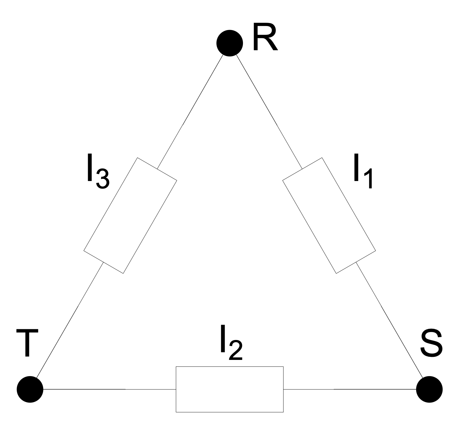
Sample 2: AC Delta Connection
Basic Circuit Diagram sample: This sample shows AC delta connection applied in three-phase electric power networks. It contains three wires carrying AC voltages, they are used for electricity transmission and distribution. In fact, it is symmetric three-phase power supply system. This AC system includes transformers.
This drawing is created using ConceptDraw DIAGRAM diagramming software enhanced with Basic Circuit Diagrams solution from ConceptDraw Solution Park.
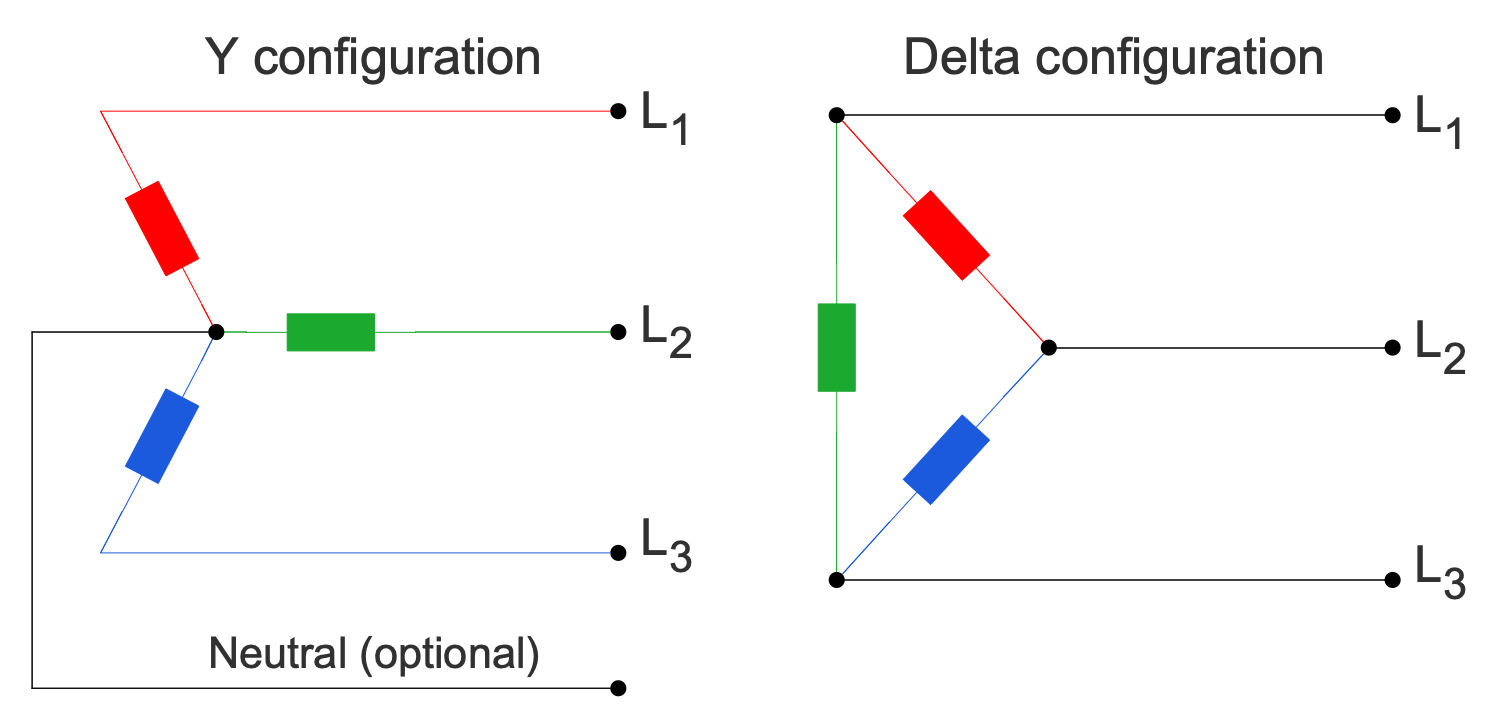
Sample 3: Basic 3-Phase Configurations
Basic Circuit Diagram sample: This sample shows two basic three-phase electric power configurations: Y (wye or star) and delta. A delta configuration uses three wires for transmission while a wye configuration may also have a fourth wire — neutral or optional. The wires are connected to a common connection point. The delta configuration is valued for the fault tolerance, its voltage or current is constant regardless of the failures in the load elements.
This drawing is created using ConceptDraw DIAGRAM diagramming software enhanced with Basic Circuit Diagrams solution from ConceptDraw Solution Park.
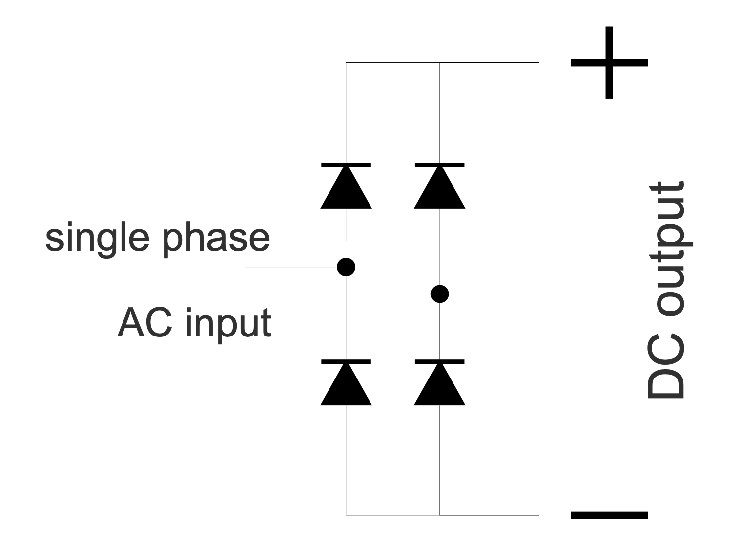
Sample 4: Bridge Rectifier for Single Phase AC
Basic Circuit Diagram sample: This sample shows a bridge rectifier for single-phase AC. A rectifier of any kind allows straightening the direction of the current. This electrical device converts alternating current (AC) to direct current (DC). AC is characterized by changing direction while DC flows only in one direction.
This drawing is created using ConceptDraw DIAGRAM diagramming software enhanced with Basic Circuit Diagrams solution from ConceptDraw Solution Park.
Sample 5: Center Tapped Delta Transformer
Basic Circuit Diagram sample: This electrical engineering sample shows a center-tapped delta transformer used to transform the 3-phase power to a split phase. These transformers are widely used in industrial regions, commercial, and high-density residential areas. The three-phase power is connected in the delta configuration and the center point of one phase is grounded.
This drawing is created using ConceptDraw DIAGRAM diagramming software enhanced with Basic Circuit Diagrams solution from ConceptDraw Solution Park.
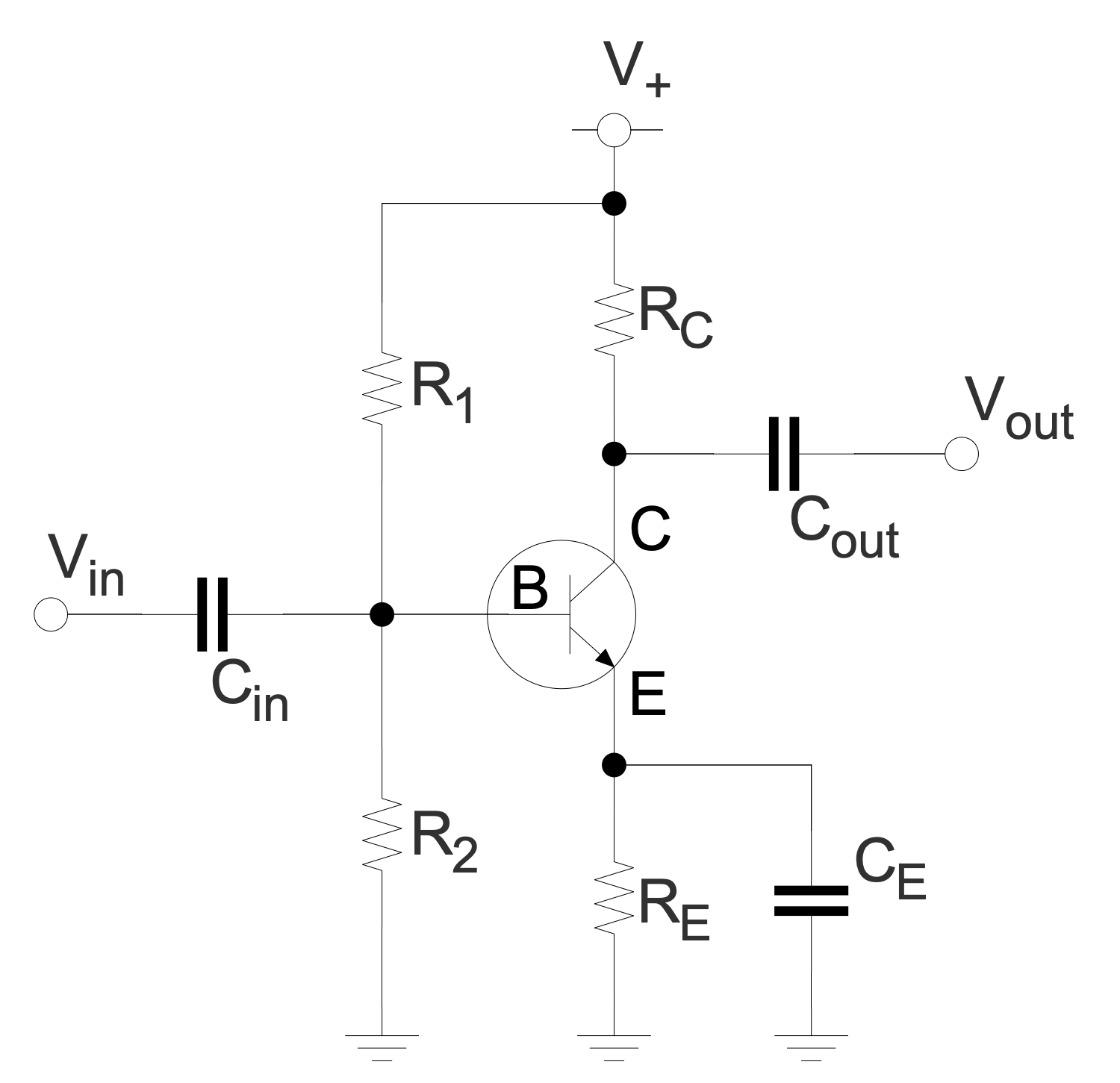
Sample 6: Common Emitter Amplifier AC Mode
Basic Circuit Diagram sample: This sample shows a common emitter amplifier circuit. It is a widely used kind of transistor circuit providing voltage gain. A transistor amplifier increases an AC input signal that interchanges between positive value and negative value.
This drawing is created using ConceptDraw DIAGRAM diagramming software enhanced with Basic Circuit Diagrams solution from ConceptDraw Solution Park.
Sample 7: Comparator
Basic Circuit Diagram sample: This sample illustrates the work of a comparator. This device is used to compare two voltages or currents, it outputs a binary digital signal 1 or 0. The value 1 corresponds to the voltage at the plus side and 0 to the voltage at the negative side.
This drawing is created using ConceptDraw DIAGRAM diagramming software enhanced with Basic Circuit Diagrams solution from ConceptDraw Solution Park.
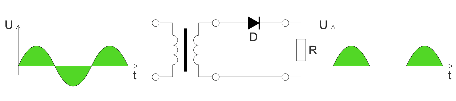
Sample 8: Half-wave Rectifier
Basic Circuit Diagram sample: This sample shows a single-phase half-wave rectifier circuit and two graphs. The first graph shows the voltage versus time before rectification, and the second after it. The half-wave rectifier includes only one rectifier element — a diode. At the output, we have a pulsating direct current. Single-phase half-wave rectifiers are widely used in modern household and industrial equipment in switching power supplies with an alternating voltage frequency of more than 10 kHz.
This drawing is created using ConceptDraw DIAGRAM diagramming software enhanced with Basic Circuit Diagrams solution from ConceptDraw Solution Park.
Sample 9: High Leg Delta Transformer
Basic Circuit Diagram sample: This sample shows a schematic of a high leg delta or orange-leg transformer. The "orange leg" name was taken from the orange color of the wire. This transformer is an extension of a split-phase electric power transformer for three phases. This mixed system is used in three-phase electric power installations to connect both the single-phase and three-phase loads.
This drawing is created using ConceptDraw DIAGRAM diagramming software enhanced with Basic Circuit Diagrams solution from ConceptDraw Solution Park.
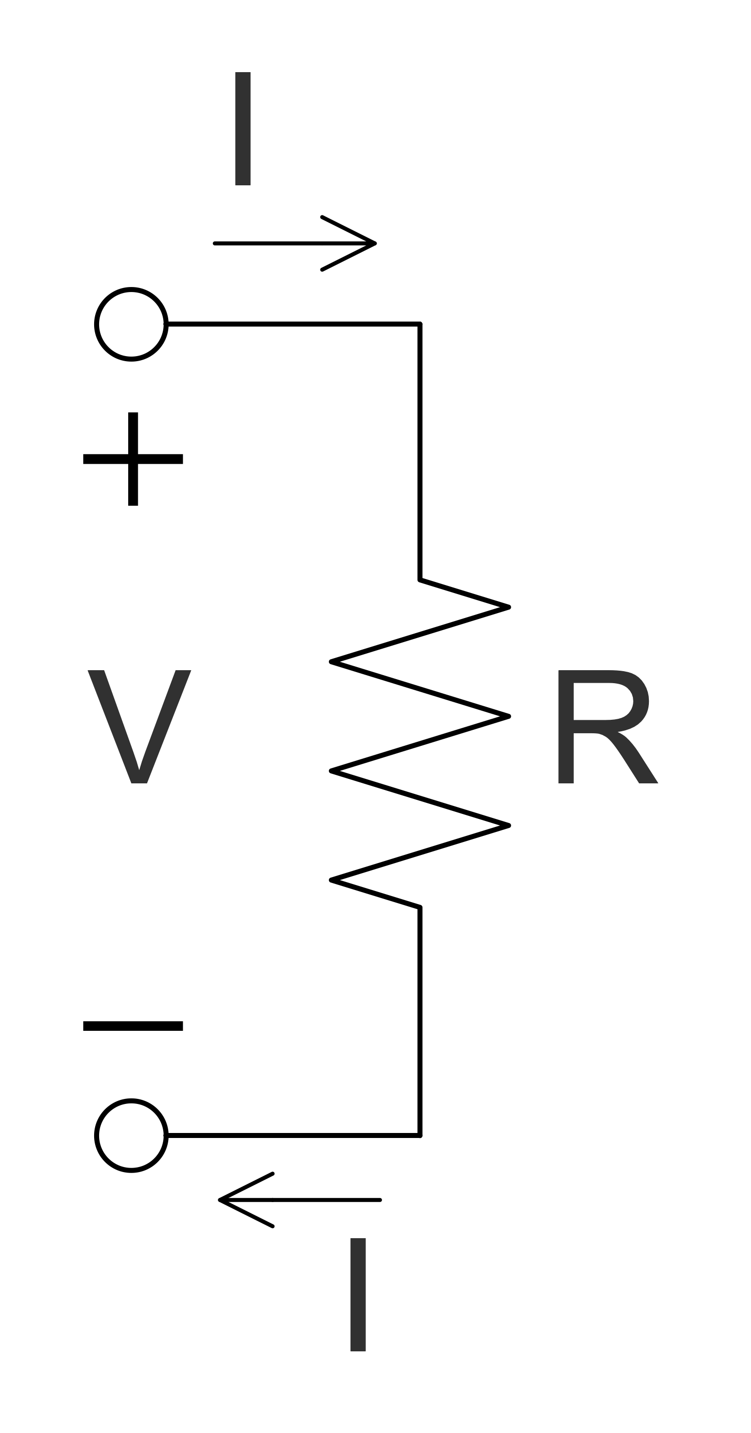
Sample 10: Ohm's law
Basic Circuit Diagram sample: This sample is an illustration of Ohm's law, established by the German physicist Georg Ohm in 1827. It determines the empirical relationship between the parameters of voltage (V), current (I), and resistance (R) in an electrical circuit and is described as follows: the formula I=V/R. Ohm's law says: the current between two points of the circuit is directly proportional to the voltage at these points and is inversely proportional to its resistance. R in this relation is constant and independent of the current, it is determined by the physical and geometric parameters of the conductor.
This drawing is created using ConceptDraw DIAGRAM diagramming software enhanced with Basic Circuit Diagrams solution from ConceptDraw Solution Park.
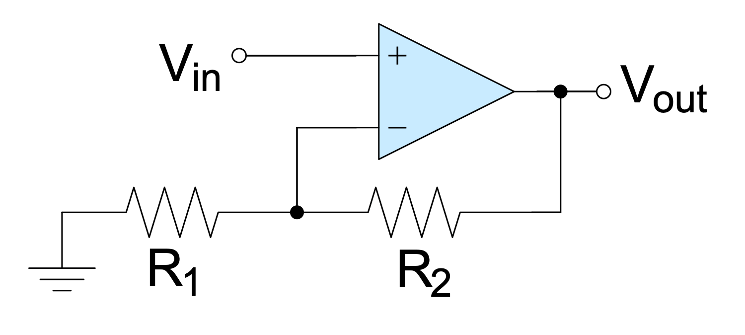
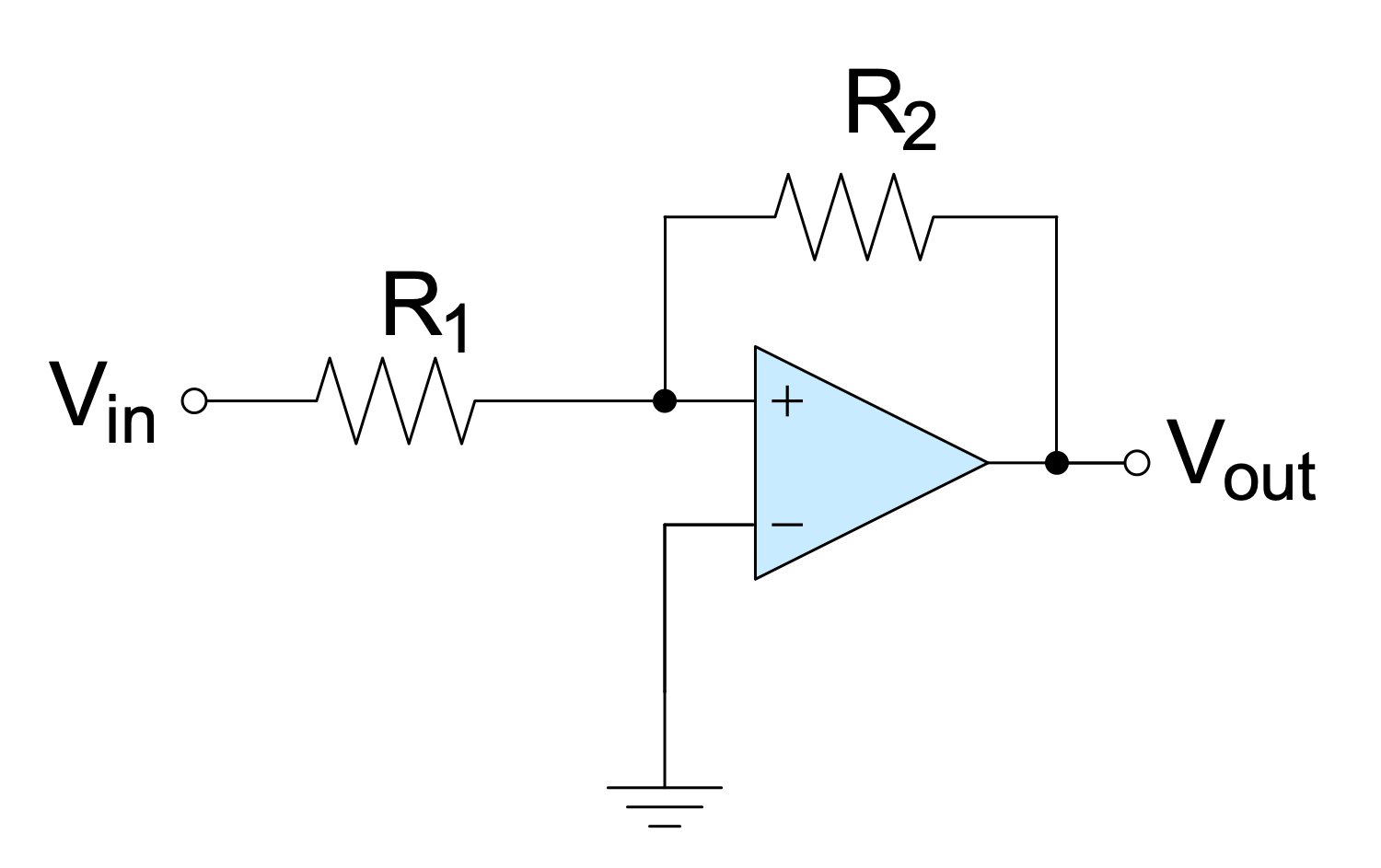
Sample 11: Op-amp Non-inverting Amplifier
Basic Circuit Diagram sample: This sample shows a non-inverting amplifier and is a special case of the differential amplifier. The circuit includes the grounded inverting input V-in and allows achieving the non-inverted output Vout at the final stage. The resistors R1 and R2 form a voltage divider. The amplified signal is delivered to the non-inverting input of the operational amplifier.
This drawing is created using ConceptDraw DIAGRAM diagramming software enhanced with Basic Circuit Diagrams solution from ConceptDraw Solution Park.
Sample 12: Op-amp Schmitt Trigger
Basic Circuit Diagram sample: This sample shows a Schmitt trigger created using an operational amplifier connected in the non-inverting amplifier configuration. It is applied to convert an analog input signal to a digital output signal. Op-amps are DC-coupled high-gain electronic voltage amplifiers. In common, they include a differential input and a single-ended output.
This drawing is created using ConceptDraw DIAGRAM diagramming software enhanced with Basic Circuit Diagrams solution from ConceptDraw Solution Park.
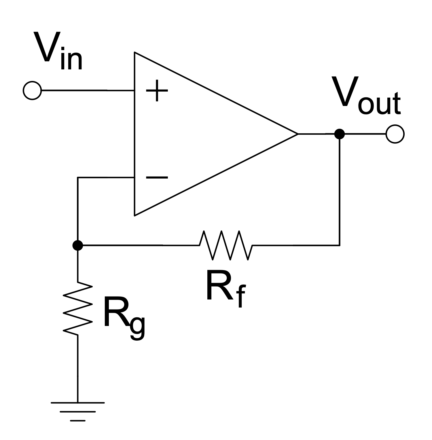
Sample 13: Op-amp with Negative Feedback Non-inverting Amplifier
Basic Circuit Diagram sample: This sample shows the non-inverting amplifier with negative feedback. Negative feedback occurs when some function of the output reduces the fluctuations in the output when it is fed back. The op-amp is most often used in the negative feedback mode and allows controlling the output. Negative feedback stabilizes the gain and increases bandwidth. Frequency distortion, noise, and non-linear distortion are reduced also due to negative feedback in the op-amp.
This drawing is created using ConceptDraw DIAGRAM diagramming software enhanced with Basic Circuit Diagrams solution from ConceptDraw Solution Park.
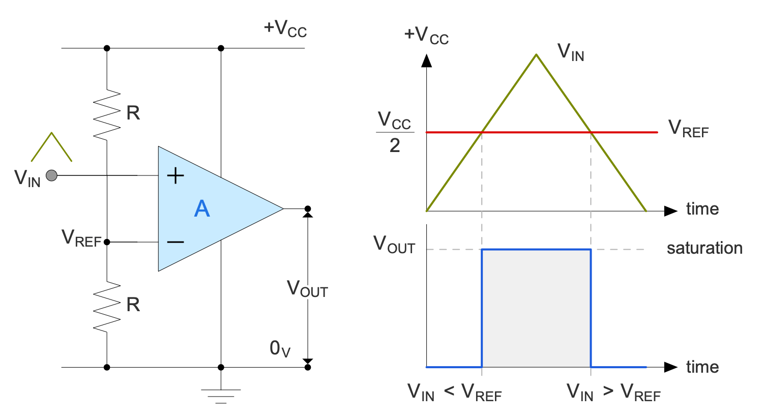
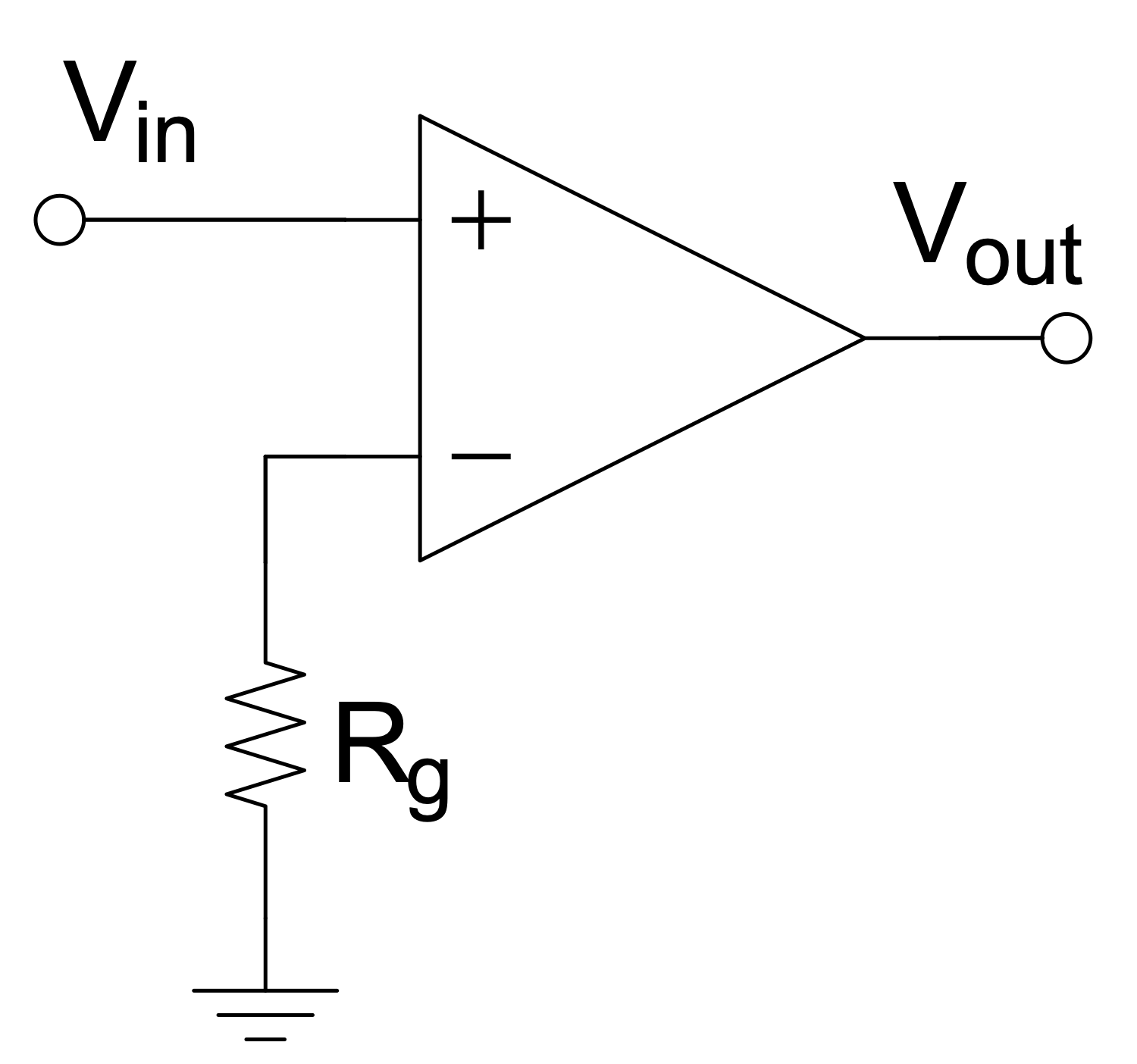
Sample 14: Op-amp without Negative Feedback a Comparator
Basic Circuit Diagram sample: This Circuit diagram sample shows the operational amplifier with one input grounded and no negative feedback. This kind of op-amp is called a comparator. It includes the inverting input and non-inverting input. The comparator compares the voltage entering at one of its inputs with the reference voltage at its other input.
This drawing is created using ConceptDraw DIAGRAM diagramming software enhanced with Basic Circuit Diagrams solution from ConceptDraw Solution Park.
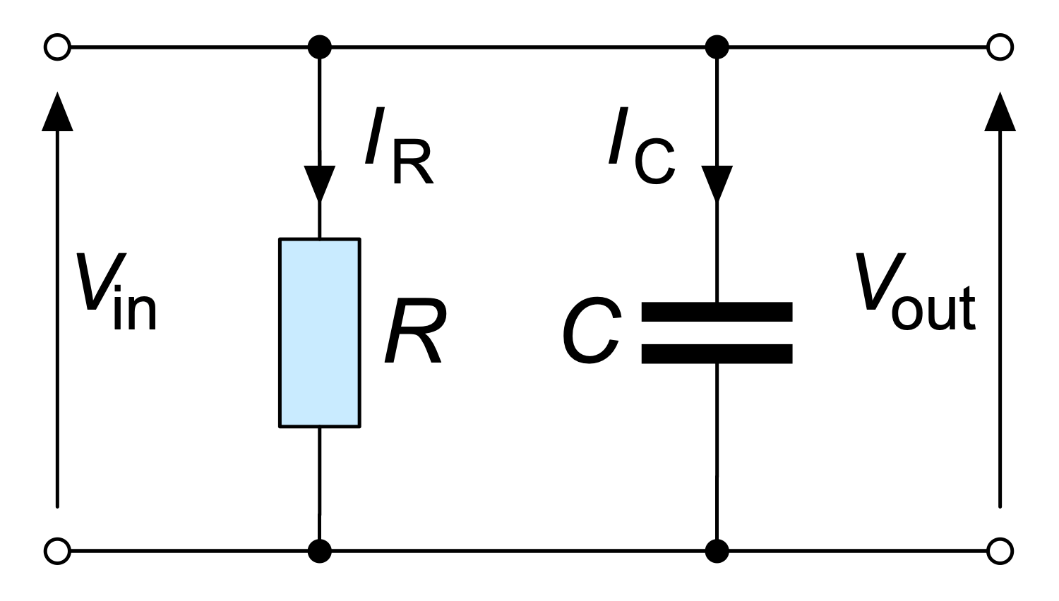
Sample 15: RC Parallel Filter
Basic Circuit Diagram sample: This sample shows a schematic of a parallel resistor-capacitor (RC) filter. It is an electric circuit including one resistor and one capacitor and driven by a voltage or current source. The resistor and capacitor are depicted using a resistor symbol and capacitor symbol correspondingly from the solution libraries. This sample shows a first-order RC circuit. RC circuits of other orders include more capacitors and resistors. RC circuits are widely used in radio electronics.
This drawing is created using ConceptDraw DIAGRAM diagramming software enhanced with Basic Circuit Diagrams solution from ConceptDraw Solution Park.
All samples are copyrighted CS Odessa's.
Usage of them is covered by Creative Commons “Attribution Non-Commercial No Derivatives” License.
The text you can find at: https://creativecommons.org/licenses/by-nc-nd/3.0