The vector stencil library "HVAC controls" contains contains 24 HVAC control symbols: sensors, actuators, timers, controllers, I/ O points.
Use it for drawing HVAC system diagrams, heating, ventilation, air conditioning, refrigeration, automated building control, and environmental control design floor
plans and equipment layouts.
"HVAC (... Heating, Ventilation and Air Conditioning) is a control system that applies regulation to a heating and/ or air conditioning system. ...
Central controllers and most terminal unit controllers are programmable, meaning the direct digital control program code may be customized for the intended use. The program features include time schedules, setpoints, controllers, logic, timers, trend logs, and alarms. The unit controllers typically have analog and digital inputs that allow measurement of the variable (temperature, humidity, or pressure) and analog and digital outputs for control of the transport medium (hot/ cold water and/ or steam). Digital inputs are typically (dry) contacts from a control device, and analog inputs are typically a voltage or current measurement from a variable (temperature, humidity, velocity, or pressure) sensing device. Digital outputs are typically relay contacts used to start and stop equipment, and analog outputs are typically voltage or current signals to control the movement of the medium (air/ water/ steam) control devices such as valves, dampers, and motors." [HVAC control system. Wikipedia]
The vector stencils example "Design elements - HVAC controls" is included in HVAC Plans solution from the Building Plans area of ConceptDraw Solution
Park.
HVAC control symbols
Electrical Symbols — Thermo

Electrical Symbols, Electrical Diagram Symbols

Electrical Symbols — Resistors

The vector stencils library "HVAC controls" contains 23 symbols of HVAC controls (sensors, actuators, timers, controllers, I/ O points). Use it for drawing HVAC system diagrams, controls drawings, and automated building control and environmental control systems design. The example "HVAC controls - Vector stencils library" was created using the ConceptDraw PRO diagramming and vector drawing software extended with the HVAC Plans solution from the Building Plans area of ConceptDraw Solution Park.
Temperature sensor

Humidity sensor

Enthalpy sensor

Pressure sensor

Flow sensor

Velocity sensor

Voltage sensor

General purpose sensor

Light sensor

Rotation sensor

Vibration sensor

Timer

Current sensor

Power sensor

Air quality sensor

Level

End switch

Smoke detector

Power connection

Actuator

I/O point

Label

Wire note

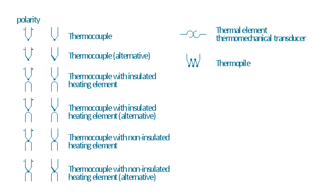
The vector stencils library "Thermo" contains 14 symbols of thermoelectric elements: thermal element, thermocouples with and without heating elements, thermoplile.
Use it for drawing electrical layouts, electronic schematics, and circuit diagrams.
"The thermoelectric effect is the direct conversion of temperature differences to electric voltage and vice versa. A thermoelectric device creates voltage when there is a different temperature on each side. Conversely, when a voltage is applied to it, it creates a temperature difference. At the atomic scale, an applied temperature gradient causes charge carriers in the material to diffuse from the hot side to the cold side.
This effect can be used to generate electricity, measure temperature or change the temperature of objects. Because the direction of heating and cooling is determined by the polarity of the applied voltage, thermoelectric devices can be used as temperature controllers.
The term "thermoelectric effect" encompasses three separately identified effects: the Seebeck effect, Peltier effect, and Thomson effect. Textbooks may refer to it as the Peltier–Seebeck effect. ...
Thermocouples and thermopiles are devices that use the Seebeck effect to measure the temperature difference between two objects, one connected to a voltmeter and the other to the probe. The temperature of the voltmeter, and hence that of the material being measured by the probe, can be measured separately using cold junction compensation techniques." [Thermoelectric effect. Wikipedia]
The shapes example "Design elements - Thermo" was drawn using the ConceptDraw PRO diagramming and vector drawing software extended with the Electrical Engineering solution from the Engineering area of ConceptDraw Solution Park.
Thermoelectric elements
Electrical Symbols — Composite Assemblies

The vector stencils library "Electrical circuits" contains 49 element symbols of electrical and electronic devices, including ignitors, starters, transmitters, circuit protectors, transducers, radio and audio equipment.
Use it for drawing electronic circuit diagrams and electrical schematics.
"An electrical network is an interconnection of electrical elements such as resistors, inductors, capacitors, voltage sources, current sources and switches. An electrical circuit is a network consisting of a closed loop, giving a return path for the current. Linear electrical networks, a special type consisting only of sources (voltage or current), linear lumped elements (resistors, capacitors, inductors), and linear distributed elements (transmission lines), have the property that signals are linearly superimposable. They are thus more easily analyzed, using powerful frequency domain methods such as Laplace transforms, to determine DC response, AC response, and transient response.
A resistive circuit is a circuit containing only resistors and ideal current and voltage sources. Analysis of resistive circuits is less complicated than analysis of circuits containing capacitors and inductors. If the sources are constant (DC) sources, the result is a DC circuit.
A network that contains active electronic components is known as an electronic circuit. Such networks are generally nonlinear and require more complex design and analysis tools." [Electrical network. Wikipedia]
The symbils example "Design elements - Electrical circuits" was drawn using the ConceptDraw PRO diagramming and vector drawing software extended with the Electrical Engineering solution from the Engineering area of ConceptDraw Solution Park.
Electrical circuit elements

Electrical Symbols, Electrical Schematic Symbols

Wiring Diagrams with ConceptDraw DIAGRAM

- Pressure Transducer Symbol
- Current And Voltage Sensor Symbol
- Current Transducer Symbol
- Symbol Air Velocity Transducer
- HVAC controls - Vector stencils library | Vibrator Sensor Symbol
- Symbols Of Temperature Sensors
- Transducer Symbol Schematic
- Water Level Sensor Symbol
- Diagram Pressure Transducer Symbol
- Analog Sensor Symbol
- Symbol Of Air Temperature Sensor
- Draw Symbol Temperature Sensors
- Level Transducer Symbol
- Symbol Of Various Tempracher Sensor
- Temperature Sensor Schematic Symbol
- Temperature Sensor Symbol
- Symbol Of Vibration Sensor
- Pressure Current Voltage Schematic Symbol
- Symbol For Temperature Timer
- Symbol Air Sensor