 Venn Diagrams
Venn Diagrams are actively used to illustrate simple set relationships in set theory and probability theory, logic and statistics, mathematics and computer science, linguistics, sociology, and marketing. Venn Diagrams are also often used to visually summarize the status and future viability of a project.
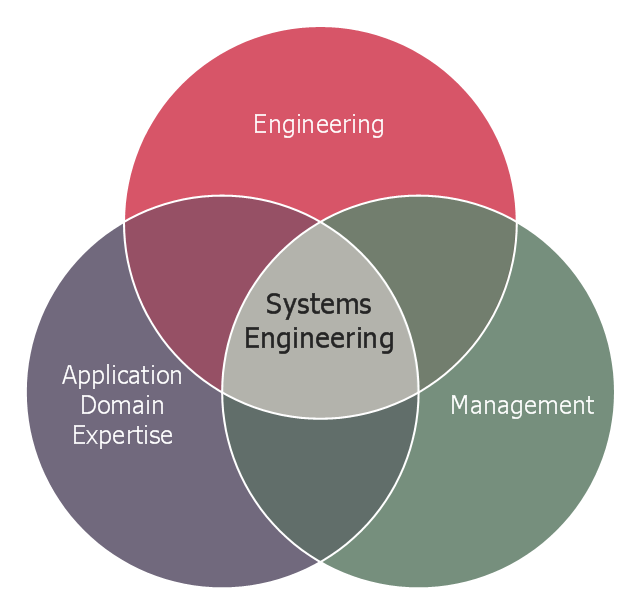
This Venn diagram sample shows the system engineering at the intersection of enginnering, management, and application domain expertise. It was designed on the base of the Venn diagram on the webpage "Intelligent Transportation Systems (ITS) ePrimer, Module 2: Systems Engineering" from the website of the Office of the Assistant Secretary for Research and Technology (OST-R), the U.S. Department of Transportation (US DOT).
"The term interdisciplinary is a fundamental concept in systems engineering. To successfully develop a system requires the application of basic engineering discipline, management discipline, and expertise in the application domain of the system. In the case of ITS, that application domain is transportation engineering. The intersection of these disciplines is the realm of systems engineering."
[pcb.its.dot.gov/ eprimer/ module2.aspx]
The Venn diagram example "Systems engineering improvement" was created using the ConceptDraw PRO diagramming and vector drawing software extended with the Venn Diagrams solution from the area "What is a Diagram" of ConceptDraw Solution Park.
Venn diagram
 Chemical and Process Engineering
This chemical engineering solution extends ConceptDraw PRO v.9.5 (or later) with process flow diagram symbols, samples, process diagrams templates and libraries of design elements for creating process and instrumentation diagrams, block flow diagrams (BFD
 Mechanical Engineering
This solution extends ConceptDraw PRO v.9 mechanical drawing software (or later) with samples of mechanical drawing symbols, templates and libraries of design elements, for help when drafting mechanical engineering drawings, or parts, assembly, pneumatic,
 Electrical Engineering
This solution extends ConceptDraw PRO v.9.5 (or later) with electrical engineering samples, electrical schematic symbols, electrical diagram symbols, templates and libraries of design elements, to help you design electrical schematics, digital and analog
HelpDesk
How to Draw a Chemical Process Flow Diagram

 Engineering Area
Solutions from the Engineering Area of ConceptDraw Solution Park collect templates, samples and libraries of vector stencils for engineering diagrams, schemes and technical drawings.
 Fault Tree Analysis Diagrams
This solution extends ConceptDraw PRO v9.5 or later with templates, fault tree analysis example, samples and a library of vector design elements for drawing FTA diagrams (or negative analytical trees), cause and effect diagrams and fault tree diagrams.
 Basic Venn Diagrams
This solution extends ConceptDraw PRO v10 (or later) with samples, templates, and libraries of vector stencils for drawing Venn Diagrams.
- Systems engineering improvement | Venn Diagrams | Venn Diagram ...
- Venn Diagram Examples For Engineers
- How To Draw A Vector Diagram Engineering Science
- Electrical Engineering | Venn Diagram Examples for Problem ...
- Wiring Diagrams with ConceptDraw PRO | Electrical Engineering ...
- Systems engineering improvement | Venn Diagrams | Functional ...
- Circuits and Logic Diagram Software | Electrical Engineering | Venn ...
- Venn Diagram In Communication Engineering
- Venn Diagram Examples for Problem Solving. Venn Diagram as a ...
- Systems engineering improvement | Venn Diagrams | Chemical and ...
- Electrical Engineering | Cooking Recipes | Plain Venn Diagram
- How to Use the Effort-Driven Scheduling Method | Electrical ...
- Entity Relationship Diagram Software Engineering | Venn Diagram ...
- Venn diagrams - Vector stencils library | Systems engineering ...
- Venn Diagrams | Systems engineering improvement | Venn Diagram ...
- Block Diagrams | Venn Diagram Of Civil Engineering
- Cubetto Flowchart | Venn Diagram For Soldier Army Engineer
- Network Diagrams In Engineering Economics
- Gate For Venn Diagram