UML Deployment Diagram. Design Elements

Diagramming Software for Design UML Collaboration Diagrams


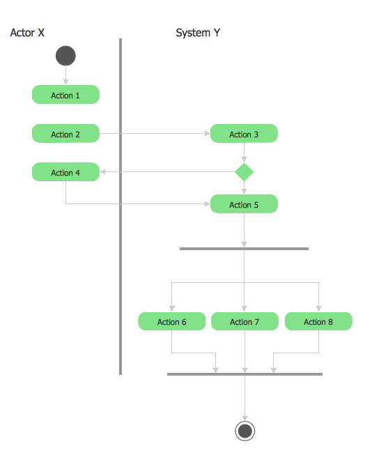
Interaction Overview Diagram

UML Component Diagram. Design Elements

"Deployment diagram shows execution architecture of systems that represent the assignment (deployment) of software artifacts to deployment targets (usually nodes).
Nodes represent either hardware devices or software execution environments. They could be connected through communication paths to create network systems of arbitrary complexity. Artifacts represent concrete elements in the physical world that are the result of a development process and are deployed on nodes.
Note, that components were directly deployed to nodes in UML 1.x deployment diagrams. In UML 2.x artifacts are deployed to nodes, and artifacts could manifest (implement) components. So components are now deployed to nodes indirectly through artifacts." [uml-diagrams.org/ deployment-diagrams.html]
The template "UML deployment diagram" for the ConceptDraw PRO diagramming and vector drawing software is included in the Rapid UML solution from the Software Development area of ConceptDraw Solution Park.
www.conceptdraw.com/ solution-park/ software-uml
UML deployment diagram

UML 2 4 Process Flow Diagram
Diagramming Software for Design UML Interaction Overview Diagrams

UML Collaboration Diagram (UML2.0)

UML Component Diagram Example - Online Shopping

Communication Diagram UML2.0 / Collaboration UML1.x

- UML Component Diagram Example - Online Shopping | UML ...
- UML Collaboration Diagram ( UML2 .0) | UML Deployment Diagram ...
- UML Deployment Diagram . Diagramming Software for Design UML ...
- UML Collaboration Diagram ( UML2 .0) | UML Component Diagram ...
- Sequence Diagram Uml 2 0
- Uml Deployment Diagram For Online Bookstore
- Rapid UML | Online Uml Drawing Tool
- Diagramming Software for Design UML Communication Diagrams ...
- UML component diagram - Template | Design elements - Bank UML ...
- UML Diagram | Communication Diagram UML2 .0 / Collaboration ...