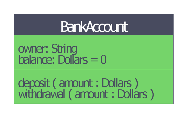
This bank account UML class diagram was redesigned from the Wikimedia Commons file: BankAccount1.svg.
[commons.wikimedia.org/ wiki/ File:BankAccount1.svg]
"Bank accounts may have a positive, or credit balance, where the bank owes money to the customer; or a negative, or debit balance, where the customer owes the bank money.
Broadly, accounts opened with the purpose of holding credit balances are referred to as deposit accounts; whilst accounts opened with the purpose of holding debit balances are referred to as loan accounts. Some accounts can switch between credit and debit balances.
Some accounts are categorized by the function rather than nature of the balance they hold, such as savings account.
All banks have their own names for the various accounts which they open for customers." [Bank account. Wikipedia]
This bank account UML class diagram example was created using the ConceptDraw PRO diagramming and vector drawing software extended with the ATM UML Diagrams solution from the Software Development area of ConceptDraw Solution Park.
Bank account UML class diagram
HelpDesk
How to Create a Bank ATM Use Case Diagram

 Data Flow Diagrams (DFD)
Data Flow Diagrams solution extends ConceptDraw PRO software with templates, samples and libraries of vector stencils for drawing the data flow diagrams (DFD).
The vector stencils library "Bank UML sequence diagram" contains 34 shapes for drawing UML sequence diagrams.
Use it for object-oriented modeling of your bank information system.
"A sequence diagram shows, as parallel vertical lines (lifelines), different processes or objects that live simultaneously, and, as horizontal arrows, the messages exchanged between them, in the order in which they occur. This allows the specification of simple runtime scenarios in a graphical manner.
Diagram building blocks.
If the lifeline is that of an object, it demonstrates a role. Leaving the instance name blank can represent anonymous and unnamed instances.
Messages, written with horizontal arrows with the message name written above them, display interaction. Solid arrow heads represent synchronous calls, open arrow heads represent asynchronous messages, and dashed lines represent reply messages. ...
Activation boxes, or method-call boxes, are opaque rectangles drawn on top of lifelines to represent that processes are being performed in response to the message (ExecutionSpecifications in UML).
Objects calling methods on themselves use messages and add new activation boxes on top of any others to indicate a further level of processing.
When an object is destroyed (removed from memory), an X is drawn on top of the lifeline, and the dashed line ceases to be drawn below it ...
A message sent from outside the diagram can be represented by a message originating from a filled-in circle (found message in UML) or from a border of the sequence diagram (gate in UML)." [Sequence diagram. Wikipedia]
This example of UML sequence diagram symbols for the ConceptDraw PRO diagramming and vector drawing software is included in the ATM UML Diagrams solution from the Software Development area of ConceptDraw Solution Park.
UML sequence diagram symbols

ATM Solutions

Process Flowchart


 Computer Network Diagrams
Computer Network Diagrams solution extends ConceptDraw PRO software with samples, templates and libraries of vector icons and objects of computer network devices and network components to help you create professional-looking Computer Network Diagrams, to plan simple home networks and complex computer network configurations for large buildings, to represent their schemes in a comprehensible graphical view, to document computer networks configurations, to depict the interactions between network's components, the used protocols and topologies, to represent physical and logical network structures, to compare visually different topologies and to depict their combinations, to represent in details the network structure with help of schemes, to study and analyze the network configurations, to communicate effectively to engineers, stakeholders and end-users, to track network working and troubleshoot, if necessary.
 PM Docs
PM Docs solution from ConceptDraw Solution Park extends ConceptDraw MINDMAP software with the ability to create and organize the project and company documentation, to structure information that relates to your project, to link the project documentation to tasks, phases, and resources. This solution contributes for improvement the project management abilities and enhancement the productivity of project team, makes it easier to locate the pertinent documentation over the life of a project, beginning from its planning, improves the document access and minimizes search time, lets to link or embed documentation into the project topics, helps create document, design professional Mind Maps, link the correct documents to keep them organized in a project, sort the project documents and visually differentiate the document types.
 Project Exchange
This solution extends ConceptDraw PROJECT and ConceptDraw MINDMAP software with the ability to import and export project data.
 Office Layout Plans
Office layouts and office plans are a special category of building plans and are often an obligatory requirement for precise and correct construction, design and exploitation office premises and business buildings. Designers and architects strive to make office plans and office floor plans simple and accurate, but at the same time unique, elegant, creative, and even extraordinary to easily increase the effectiveness of the work while attracting a large number of clients.
 Crystal Mapping
With Crystal Mapping all goals and relevant information can be observed in one radiant dashboard.
 PM Easy
PM Easy solution extends the ConceptDraw PROJECT functionality with an ability to support neutral methodology of project management and to quickly start a project by listing the task relationships and dependencies, that makes the iterative planning much easier. The project management tool and available visual tools, such as mind mapping, increase the effectiveness of tracking and analysis your project tasks. PM Easy solution from ConceptDraw Solution Park is mainly targeted at project managers in small or medium-sized companies, allowing them to make the project plan and execute projects using mind mapping technique, to implement planning using mind mapping, and to track tasks using ConceptDraw PROJECT application.
- Class UML Diagram for Bank Account System | UML for Bank | UML ...
- Draw A Uml Class Diagram For Opening A Bank Account
- UML use case diagram - Banking system
- Class UML Diagram for Bank Account System | Bank UML Diagram ...
- Class UML Diagram for Bank Account System | UML package ...
- UML for Bank | ATM UML Diagrams | UML use case diagram ...
- DFD - Process of account receivable | Data Flow Diagram Process ...
- UML for Bank | How to Create a Bank ATM Use Case Diagram ...
- UML for Bank | UML use case diagram - Banking system | Class ...
- UML use case diagram - Banking system | UML for Bank | Class ...
- UML Activity Diagram
- UML for Bank | UML use case diagram - Banking system | UML ...
- UML use case diagram - Banking system | Bank Sequence Diagram ...
- UML activity diagram - Cash withdrawal from ATM | UML Activity ...
- UML for Bank | UML use case diagram - Banking system | Bank UML ...
- Business Process To Model The Flow For Bank Account Opening
- Entity-Relationship Diagram (ERD) | UML use case diagram ...
- Bank System | UML use case diagram - Banking system | Data Flow ...
- Cisco Network Diagrams | Bank Sequence Diagram | UML activity ...
- Type Of Uml Diagrams