UML Component Diagram. Design Elements


Database Diagram Tool
Example of DFD for Online Store (Data Flow Diagram)


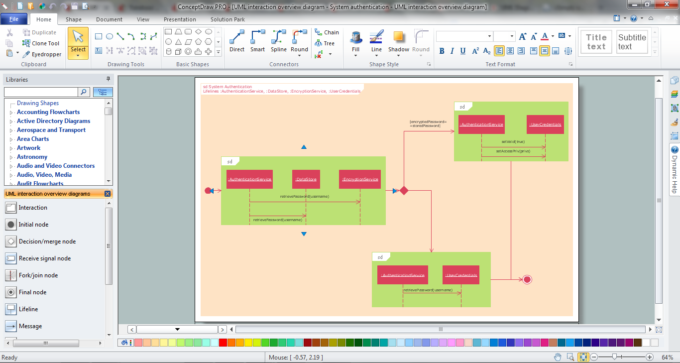
Interaction Overview Diagram

Data Flow Diagrams

Data Flow Diagram Model

Components of ER Diagram

UML Class Diagram Notation

Bank UML Diagram

UML Sample Project

- Server hardware - Rack diagram | UML component diagram - Start ...
- Design elements - Bank UML deployment diagram | UML ...
- ConceptDraw PRO Database Modeling Software | UML Component ...
- UML Component Diagram Example - Online Shopping | Entity ...
- UML component diagram - Start server | UML communication ...
- Design elements - Bank UML component diagram | Component ...
- Database Component For Online Shopping Pdf
- Example of DFD for Online Store ( Data Flow Diagram ) DFD ...
- Data modeling with ConceptDraw PRO | Uml Database Notation
- UML Deployment Diagram . Diagramming Software for Design UML ...