Retract resistor check valve application: pneumatic cylinder, piston driven by Compressed air through 2 Retract resistor check valves.
"A check valve, clack valve, non-return valve or one-way valve is a valve that normally allows fluid (liquid or gas) to flow through it in only one direction.
Check valves are two-port valves, meaning they have two openings in the body, one for fluid to enter and the other for fluid to leave. There are various types of check valves used in a wide variety of applications. Check valves are often part of common household items. Although they are available in a wide range of sizes and costs, check valves generally are very small, simple, or inexpensive. Check valves work automatically and most are not controlled by a person or any external control; accordingly, most do not have any valve handle or stem. The bodies (external shells) of most check valves are made of plastic or metal.
An important concept in check valves is the cracking pressure which is the minimum upstream pressure at which the valve will operate. Typically the check valve is designed for and can therefore be specified for a specific cracking pressure.
Heart valves are essentially inlet and outlet check valves for the heart ventricles, since the ventricles act as pumps." [Check valve. Wikipedia]
This hydraulic schematic example was redrawn using ConceptDraw PRO diagramming and vector drawing software from the Wikimedia Commons file: Retract resistor check valve application.png.
[commons.wikimedia.org/ wiki/ File:Retract_ resistor_ check_ valve_ application.png]
The hydraulic engineering drawing example "Retract resistor check valve application" was created using the ConceptDraw PRO diagramming and vector drawing software extended with the Mechanical Engineering solution from the Engineering area of ConceptDraw Solution Park.
Hydraulic schematic

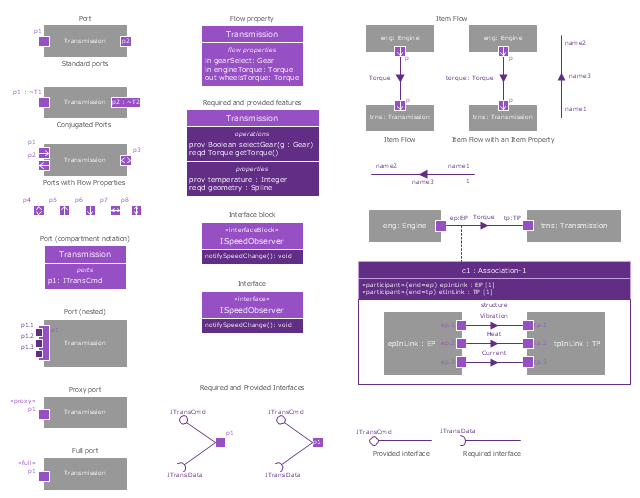
The vector stencils library "Ports and Flows" contains 26 SysML symbols.
Use it to design your SysML diagrams using ConceptDraw PRO diagramming and vector drawing software.
"The main motivation for specifying ports and flows is to enable design of modular, reusable blocks with clearly defined
ways of connecting and interacting with their context of use. This clause extends UML ports to support nested ports, and
extends blocks to support flow properties, and required and provided features, including blocks that type ports. Ports can be typed by blocks that support operations, receptions, and properties as in UML. SysML defines a specialized form of Block (InterfaceBlock) that can be used to support nested ports. SysML identifies two kinds of ports, one that exposes
features of the owning block or its internal parts (proxy ports), and another that supports its own features (full ports). Default compatibility rules are defined for connecting blocks used in composite structure, including parts and ports, with association blocks available to define more specific ways of doing this. These additional capabilities in SysML enable modelers to specify a wide variety of interconnectable components, which can be implemented through many engineering and social techniques, such as software, electrical or mechanical components, and human organizations. This clause also extends UML information flows for specifying item flows across connectors and associations." [www.omg.org/ spec/ SysML/ 1.3/ PDF]
The SysML shapes example "Design elements - Ports and Flows" is included in the SysML solution from the Software Development area of ConceptDraw Solution Park.
SysML ports and flows symbols
Network Glossary Definition


 Audit Flowcharts
Audit flowcharts solution extends ConceptDraw DIAGRAM software with templates, samples and library of vector stencils for drawing the audit and fiscal flow charts.
 Computer Network Diagrams
Computer Network Diagrams solution extends ConceptDraw DIAGRAM software with samples, templates and libraries of vector icons and objects of computer network devices and network components to help you create professional-looking Computer Network Diagrams, to plan simple home networks and complex computer network configurations for large buildings, to represent their schemes in a comprehensible graphical view, to document computer networks configurations, to depict the interactions between network's components, the used protocols and topologies, to represent physical and logical network structures, to compare visually different topologies and to depict their combinations, to represent in details the network structure with help of schemes, to study and analyze the network configurations, to communicate effectively to engineers, stakeholders and end-users, to track network working and troubleshoot, if necessary.
 Flowcharts
The Flowcharts solution for ConceptDraw DIAGRAM is a comprehensive set of examples and samples in several varied color themes for professionals that need to represent graphically a process. Solution value is added by the basic flow chart template and shapes' libraries of flowchart notation. ConceptDraw DIAGRAM flow chart creator lets one depict the processes of any complexity and length, as well as design the Flowchart either vertically or horizontally.
 Cross-Functional Flowcharts
Cross-functional flowcharts are powerful and useful tool for visualizing and analyzing complex business processes which requires involvement of multiple people, teams or even departments. They let clearly represent a sequence of the process steps, the order of operations, relationships between processes and responsible functional units (such as departments or positions).
 Floor Plans
Construction, repair and remodeling of the home, flat, office, or any other building or premise begins with the development of detailed building plan and floor plans. Correct and quick visualization of the building ideas is important for further construction of any building.
 Business Process Mapping
The Business Process Mapping solution for ConceptDraw DIAGRAM is for users involved in process mapping and creating SIPOC diagrams.
 Reflected Ceiling Plans
Reflected Ceiling Plans solution extends greatly the ConceptDraw DIAGRAM functionality with samples, templates and libraries of design elements for displaying the ceiling ideas for living room, bedroom, classroom, office, shop, restaurant, and many other premises. It is an effective tool for architects, designers, builders, electricians, and other building-related people to represent their ceiling design ideas and create Reflected Ceiling plan or Reflective Ceiling plan, showing the location of light fixtures, lighting panels, drywall or t-bar ceiling patterns, HVAC grilles or diffusers that may be suspended from the ceiling. Being professional-looking and vivid, these plans perfectly reflect your ceiling ideas and can be presented to the client, in reports, in presentations, on discussions with colleagues, or successfully published in modern print or web editions.
 Interactive Voice Response Diagrams
Interactive Voice Response Diagrams solution extends ConceptDraw DIAGRAM software with samples, templates and libraries of ready-to-use vector stencils that help create Interactive Voice Response (IVR) diagrams illustrating in details a work of interactive voice response system, the IVR system’s logical and physical structure, Voice-over-Internet Protocol (VoIP) diagrams, and Action VoIP diagrams with representing voice actions on them, to visualize how the computers interact with callers through voice recognition and dual-tone multi-frequency signaling (DTMF) keypad inputs.
- Mechanical Drawing Symbols | Mechanical Engineering ...
- Mechanical Engineering Symbols And Their Meanings
- Mechanical Engineering Drawing Symbols And Their Meanings Pdf
- Mechanical Engineering Drawing Symbols And Their Meanings
- Basic Flowchart Symbols and Meaning | Technical Drawing ...
- Engineering Design Symbols And Their Meanings
- Mechanical Drawing Symbols | Process Flow Diagram Symbols ...
- Engineering Symbols And Meanings
- Mechanical Engineering Drawing All Symbols And Discription
- Mechanical Drawing Symbols | Technical Drawing Software ...
- Mechanical Drawing Symbols | Basic Flowchart Symbols and ...
- Engineering Drawing Symbols And Their Meanings
- Mechanical Drawing Symbols | Technical Drawing Software | Entity ...
- Mechanical Drawing Symbols | Mechanical Engineering ...
- Mechanical Drawing Symbols | Basic Flowchart Symbols and ...
- Mechanical Drawing Symbols | Basic Flowchart Symbols and ...
- Engineering Graphics Diagram Symbols With Meaning
- Types Of Mechanical Drawing Symbols In Engineering Drawing ...
- Technical Drawing Software | Mechanical Drawing Symbols ...
- Mechanical Related Quality Control Symbols And Their Meaning In ...