This electrical floor plan sample shows the lighting and switch layout.
"In building wiring, a light switch is a switch, most commonly used to operate electric lights, permanently connected equipment, or electrical outlets. Portable lamps such as table lamps will have a light switch mounted on the socket, base, or in-line with the cord. Manually operated on/ off switches may be substituted by remote control switches, or light dimmers that allow controlling the brightness of lamps as well as turning them on or off. Light switches are also found in flashlights and automobiles and other vehicles." [Light switch. Wikipedia]
The electrical floor plan example "Lighting and switch layout" was created using the ConceptDraw PRO diagramming and vector drawing software extended with the Electric and Telecom Plans solution from the Building plans area of ConceptDraw Solution Park.
Electrical floor plan

How To use House Electrical Plan Software


Home Electrical Plan

Electrical Symbols — Switches and Relays

This cafe electrical floor plan sample shows the outlet and switch layout.
"An electrical drawing, is a type of technical drawing that shows information about power, lighting, and communication for an engineering or architectural project. Any electrical working drawing consists of "lines, symbols, dimensions, and notations to accurately convey an engineering's design to the workers, who install the electrical system on the job".
A complete set of working drawings for the average electrical system in large projects usually consists of:
(1) A plot plan showing the building's location and outside electrical wiring.
(2) Floor plans showing the location of electrical systems on every floor.
(3) Power-riser diagrams showing panel boards.
(4) Control wiring diagrams.
(5) Schedules and other information in combination with construction drawings.
Electrical drafters prepare wiring and layout diagrams used by workers who erect, install, and repair electrical equipment and wiring in communication centers, power plants, electrical distribution systems, and buildings." [Electrical drawing. Wikipedia]
The outlet and switch layout example "Cafe electrical floor plan" was created using the ConceptDraw PRO diagramming and vector drawing software extended with the Electric and Telecom Plans solution from the Building Plans area of ConceptDraw Solution Park.
Outlet and switch layout

How To use Switches in Network Diagram


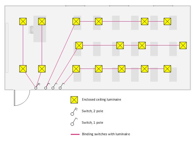
This electrical floor plan sample shows the lighting layout on the classroom reflected ceiling plan.
"Architectural lighting design is a field within architecture and architectural engineering that concerns itself primarily with the illumination of buildings. The objective of architectural lighting design is to obtain sufficient light for the purposes of the building, balancing factors of initial and operating cost, appearance, and energy efficiency. Lighting designers are often specialists who must understand the physics of light production and distribution, and the physiology and psychology of light perception by humans. Architectural lighting design is generally concerned with the permanent illumination of a structure. Concert and theatrical lighting have different purposes and practitioners." [Architectural lighting design. Wikipedia]
The electrical floor plan example "Classroom lighting - Reflected ceiling plan" was created using the ConceptDraw PRO diagramming and vector drawing software extended with the Electric and Telecom Plans solution from the Building plans area of ConceptDraw Solution Park.
Electrical floor plan
Electrical Symbols, Electrical Diagram Symbols

The vector stencils library "Network layout floorplan" contain 34 symbol icons for drawing computer network floor plans and communication equipment and cabling layouts.
"Networking hardware may also be known as network equipment or computer networking devices. Units which are the last receiver or generate data are called hosts or data terminal equipment.
All these terms refer to devices facilitating the use of a computer network. Specifically, they mediate data in a computer network. ...
Typically, networking hardware includes gateways, routers, network bridges, switches, hubs, and repeaters. But it also includes hybrid network devices such as multilayer switches, protocol converters, bridge routers, proxy servers, firewalls, network address translators, multiplexers, network interface controllers, wireless network interface controllers, modems, ISDN terminal adapters, line drivers, wireless access points, networking cables and other related hardware.
The most common kind of networking hardware today is a copper-based Ethernet adapter because of its standard inclusion on most modern computer systems. Wireless networking has, however, become increasingly popular, especially for portable and handheld devices.
Other hardware prevalent in computer networking includes data center equipment (such as file servers, database servers and storage areas), network services (such as DNS, DHCP, email, etc.) as well as devices which assure content delivery." [Networking hardware. Wikipedia]
The shapes example "Design elements - Network layout floorplan" was created using the ConceptDraw PRO diagramming and vector drawing software extended with the Network Layout Floor Plans solution from the Computer and Networks area of ConceptDraw Solution Park.
Network layout floor plan symbols

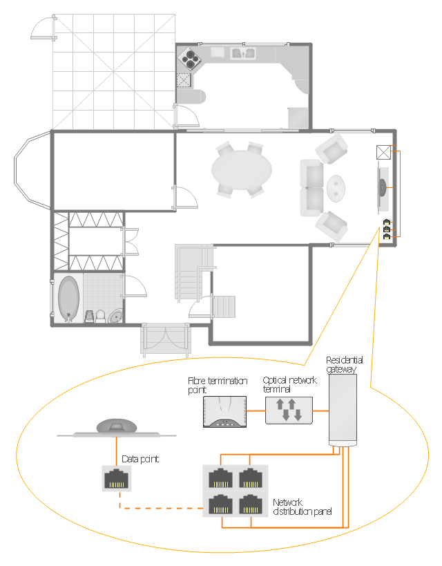
"A home network or home area network (HAN) is a type of local area network that develops from the need to facilitate communication and interoperability among digital devices present inside or within the close vicinity of a home. Devices capable of participating in this network - smart devices such as network printers and handheld mobile computers - often gain enhanced emergent capabilities through their ability to interact. These additional capabilities can then be used to increase the quality of life inside the home in a variety of ways, such as automation of repetitious tasks, increased personal productivity, enhanced home security, and easier access to entertainment." [Home network. Wikipedia]
The HAN equipment layout floorplan example "Home network plan" was created using the ConceptDraw PRO diagramming and vector drawing software extended with the Network Layout Floor Plans solution from the Computer and Networks area of ConceptDraw Solution Park.
The HAN equipment layout floorplan example "Home network plan" was created using the ConceptDraw PRO diagramming and vector drawing software extended with the Network Layout Floor Plans solution from the Computer and Networks area of ConceptDraw Solution Park.
HAN layout floorplan
- Lighting and switch layout | Classroom lighting - Reflected ceiling ...
- Lighting and switch layout | Reflected ceiling plan | Classroom ...
- Air Conditioner Switch Symbol
- Lighting and switch layout | Design elements - Electrical and ...
- HVAC Business Plan | HVAC Plans | Air Cond Switch Symbol
- How To use House Electrical Plan Software | Fan Switch Symbol In ...
- Circuit Symbol Of A Dimmer Switch
- Electrical Symbol Of Main Switch Power
- Electrical Symbol For Light Switch
- Two Way Switch Plan