How To use House Electrical Plan Software


Electrical Symbols, Electrical Diagram Symbols

Electrical Symbols — Terminals and Connectors

Electrical Symbols — Switches and Relays

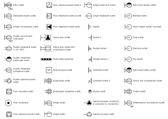
The vector stencil library "RCP-Electrical outlets" contains 43 socket symbols.
Use it to design your reflected ceiling plan with ConceptDraw DIAGRAM software.
"An electrical outlet or receptacle is a socket that connects an electrical device to an electricity supply. In buildings, electrical outlets are usually installed in the wall, although they can also be installed in the floor. Occasionally, they are found in the ceiling for powering devices such as garage door openers or neon signs in storefront windows. Different countries often have different outlet types and voltages. Adapters are available to convert between the different types." [Electrical outlet. Simple Wikipedia]
The receptacle symbols example "Design Elements - RCP-Electrical outlets" is included in Reflected Ceiling Plans solution from the Building Plans area of ConceptDraw Solution Park.
Vector stencils
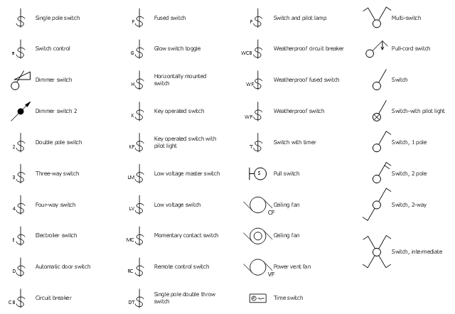
The vector stencil library "RCP-Electrical switches" contains 35 light switch symbols.
Use it to design your reflected ceiling plan with ConceptDraw DIAGRAM software.
"In electrical engineering, a switch is an electrical component that can "make" or "break" an electrical circuit, interrupting the current or diverting it from one conductor to another. The mechanism of a switch removes or restores the conducting path in a circuit when it is operated. It may be operated manually, for example, a light switch or a keyboard button, may be operated by a moving object such as a door, or may be operated by some sensing element for pressure, temperature or flow. A switch will have one or more sets of contacts, which may operate simultaneously, sequentially, or alternately." [Switch. Wikipedia]
"In electrical wiring, a light switch is a switch most commonly used to operate electric lights, permanently connected equipment, or electrical outlets. Portable lamps such as table lamps may have a light switch mounted on the socket, base, or in-line with the cord. Manually operated on/ off switches may be substituted by dimmer switches that allow controlling the brightness of lamps as well as turning them on or off, time-controlled switches, occupancy-sensing switches, and remotely controlled switches and dimmers." [Light switch. Wikipedia]
The light switch symbols example "Design Elements - RCP-Electrical switches" is included in Reflected Ceiling Plans solution from the Building Plans area of ConceptDraw Solution Park.
Vector stencils
Cisco Network Design. Cisco icons, shapes, stencils, symbols and design elements

The vector stencils library "Electrical and telecom" contains 83 symbols of electrical and telecommunication equipment.
Use these shapes for drawing electrical and telecom system design floor plans, cabling layout schemes, and wiring diagrams in the ConceptDraw PRO diagramming and vector drawing software.
The vector stencils library "Electrical and telecom" is included in the Electric and Telecom Plans solution from the Building Plans area of ConceptDraw Solution Park.
Luminaire ceiling mount

Enclosed ceiling luminaire

Wall light

1-light bar

2-light bar

4-light bar

6-light bar

8-light bar

Down lighter

Outdoor lightning

Outdoor lightning, bollard

Batten fluorescent, 1 lamp

Batten fluorescent, 2 lamps

Batten fluorescent, 3 lamps

Batten fluorescent, 4 lamps

Surface Fluorescent Light

Modular fluorescent fitting

Modular fluorescent fitting, inverter

Modular fluorescent fitting 2

Pull-cord switch

Emergency light

Emergency light 2

Emergency sign

Switch

Switch, 1 pole

Switch, 2 pole

Switch, 2-way

Multi-switch

Switch, intermediate

Dimmer switch

Dimmer switch 2

Socket

Socket 2

Switched socket

Switched socket 2

Double socket

Double socket 2

Socket outlet

Telephone outlet

Telephone outlet 2

Stereo outlet

Television outlet

Service panel, surface

Service panel, inset

Thermostat

Ceiling fan

Hold open unit

Detector

Fire alarm

City Fire Alarm Station

Fire Alarm Station

Fire Alarm Bell

Fire Alarm Central Station

Automatic Fire Alarm Device

Main control

Ground

Doorbell

Push Button

Buzzer

Annunciator

Horn

Maid's Signal Plug

Signal Central Station

Doorbell Chime

Doorbell Transformer

Magnetic Door Hold

Intercom

Telephone Key System

Digital Satellite System

Inside Antenna

Outside Antenna

Electric Motors

Single Phase

Three of Poly Phase

Wall Mounted Electrical Junction Box for Hardware

Wall Mounted Telephone/Data Junction Box for Hardware

Card Reader Access System

Emergency Release Button

Motion Sensor

Electric Door Opener

Watchman's Station

Watchman's Central Station

Battery

The vector stencils library "Network layout floorplan" contain 34 symbol icons for drawing computer network floor plans and communication equipment and cabling layouts.
"Networking hardware may also be known as network equipment or computer networking devices. Units which are the last receiver or generate data are called hosts or data terminal equipment.
All these terms refer to devices facilitating the use of a computer network. Specifically, they mediate data in a computer network. ...
Typically, networking hardware includes gateways, routers, network bridges, switches, hubs, and repeaters. But it also includes hybrid network devices such as multilayer switches, protocol converters, bridge routers, proxy servers, firewalls, network address translators, multiplexers, network interface controllers, wireless network interface controllers, modems, ISDN terminal adapters, line drivers, wireless access points, networking cables and other related hardware.
The most common kind of networking hardware today is a copper-based Ethernet adapter because of its standard inclusion on most modern computer systems. Wireless networking has, however, become increasingly popular, especially for portable and handheld devices.
Other hardware prevalent in computer networking includes data center equipment (such as file servers, database servers and storage areas), network services (such as DNS, DHCP, email, etc.) as well as devices which assure content delivery." [Networking hardware. Wikipedia]
The shapes example "Design elements - Network layout floorplan" was created using the ConceptDraw PRO diagramming and vector drawing software extended with the Network Layout Floor Plans solution from the Computer and Networks area of ConceptDraw Solution Park.
Network layout floor plan symbols

Electrical Symbols — Inductors

- Switch Socket Symbols
- Symbols Sockets Switches
- Electrical Symbols , Electrical Diagram Symbols | Electrical Symbols ...
- Lighting and switch layout | Lighting Plan Symbols Sockets
- Electric and Telecom Plans | House Wiring Symbol Socket Switch
- Symbol For Electric Cooker Air Condition Switch And Water Heater
- Circuit Symbol Of Cooker Switches
- Electrical Symbols , Electrical Diagram Symbols | 15 Amp Socket ...
- Air Conditioner Switch Symbol
- Symbol Of Intermediate Switch