How To use House Electrical Plan Software


Building Drawing Software for Design Office Layout Plan


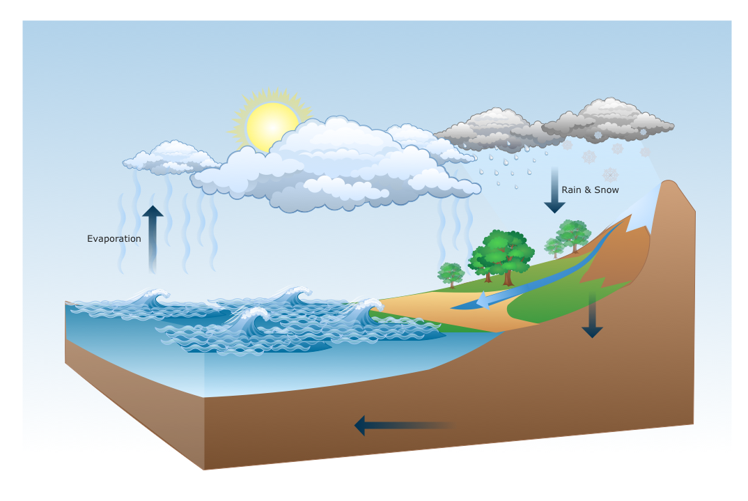
Drawing a Nature Scene
Process Flowchart


Electrical Symbols, Electrical Diagram Symbols

The vector stencils library "Dimensioning and tolerancing" contains 45 symbols of geometric dimensions and mechanical tolerances, geometric symbols, callouts, and text boxes and inserts.
Use these geometric dimensioning and tolerancing (GD&T) shapes to create annotated mechanical drawings.
"Geometric dimensioning and tolerancing (GD&T) is a system for defining and communicating engineering tolerances. It uses a symbolic language on engineering drawings and computer-generated three-dimensional solid models that explicitly describes nominal geometry and its allowable variation. It tells the manufacturing staff and machines what degree of accuracy and precision is needed on each controlled feature of the part. GD&T is used to define the nominal (theoretically perfect) geometry of parts and assemblies, to define the allowable variation in form and possible size of individual features, and to define the allowable variation between features." [Geometric dimensioning and tolerancing. Wikipedia]
The shapes example "Design elements - Dimensioning and tolerancing" was created using the ConceptDraw PRO diagramming and vector drawing software extended with the Mechanical Engineering solution from the ConceptDraw Solution Park.
Dimensioning and tolerancing symbols

The vector stencils library "Vessels" contains 40 symbols of vessels, containers, tanks, drums, and basins.
Use these shapes for drawing process flow diagrams (PFD), materials handling systems, and feed systems in industrial and manufacturing processes.
"A pressure vessel is a closed container designed to hold gases or liquids at a pressure substantially different from the ambient pressure.
The pressure differential is dangerous and fatal accidents have occurred in the history of pressure vessel development and operation. Consequently, pressure vessel design, manufacture, and operation are regulated by engineering authorities backed by legislation. For these reasons, the definition of a pressure vessel varies from country to country, but involves parameters such as maximum safe operating pressure and temperature." [Pressure vessel. Wikipedia]
The example "Design elements - Vessels" was created using the ConceptDraw PRO diagramming and vector drawing software extended with the Chemical and Process Engineering solution from the Engineering area of ConceptDraw Solution Park.
Vessel symbols

Interior Design. Machines and Equipment — Design Elements

Interior Design. Office Layout Plan Design Element

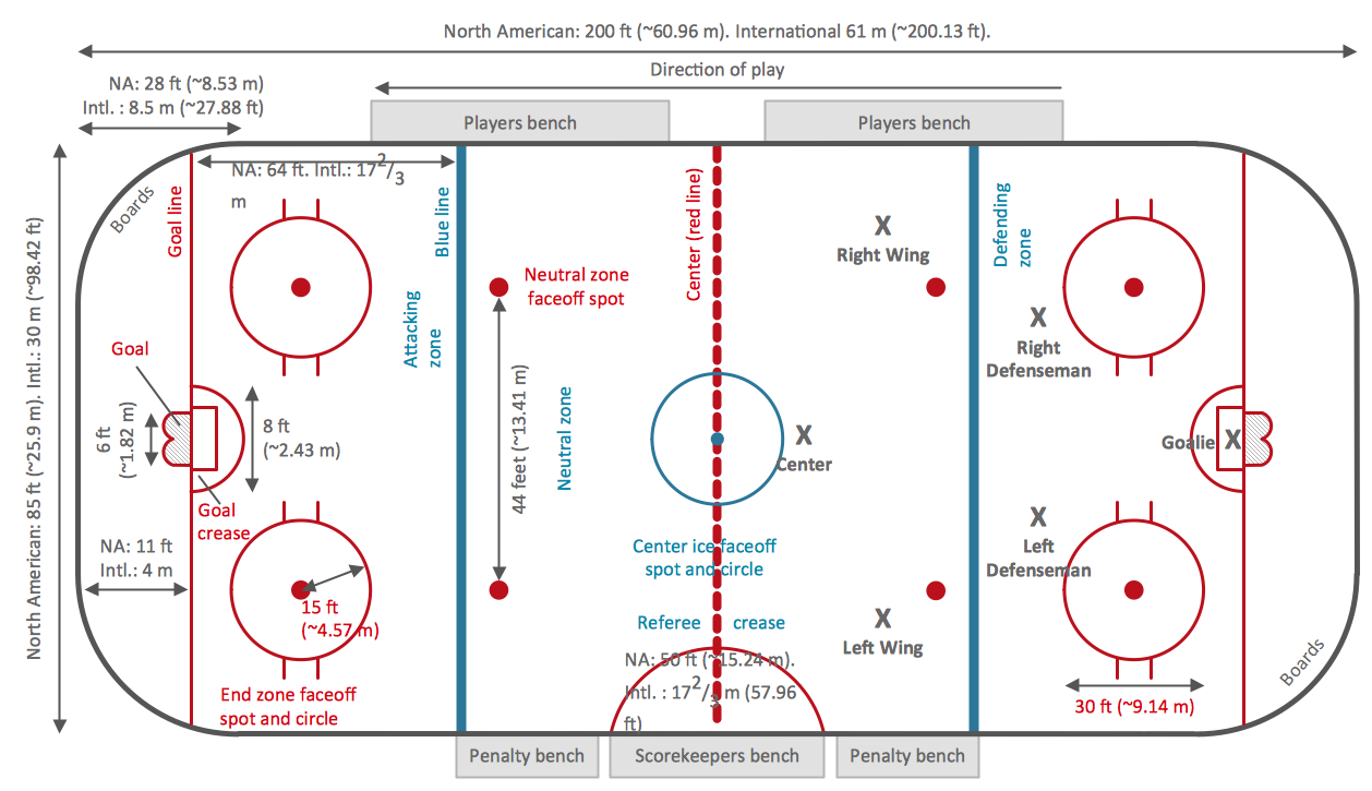
Ice Hockey Rink Dimensions
- Engineering Drawing Dimension Symbols
- Surface Finish Symbols In Engineering Drawing
- Symbol Of Engineering Graphics Surface Roughness
- Geometric Symbols Of Machine Design
- Mechanical Drawing Symbols | Design elements - Dimensioning ...
- Symbols On Pressure Vessel
- Use Of Dimensional Tolerances Geometrical Tolerances And ...
- Top 5 Android Flow Chart Apps | Machine Symbols In Drawing
- Mechanical Drawing Symbols | Technical Drawing Software | How ...
- Mechanical Drawing Symbols | Design elements - Bearings ...