"The symbols and conventions used in welding documentation are specified in national and international standards such as ISO 2553 Welded, brazed and soldered joints -- Symbolic representation on drawings and ISO 4063 Welding and allied processes -- Nomenclature of processes and reference numbers. The US standard symbols are outlined by the American National Standards Institute and the American Welding Society and are noted as "ANSI/ AWS".
In engineering drawings, each weld is conventionally identified by an arrow which points to the joint to be welded. The arrow is annotated with letters, numbers and symbols which indicate the exact specification of the weld. In complex applications, such as those involving alloys other than mild steel, more information may be called for than can comfortably be indicated using the symbols alone. Annotations are used in these cases." [Symbols and conventions used in welding documentation. Wikipedia]
The example chart "Elements of welding symbol" is redesigned using the ConceptDraw PRO diagramming and vector drawing software from the Wikipedia file: Elements of a welding symbol.PNG.
[en.wikipedia.org/ wiki/ File:Elements_ of_ a_ welding_ symbol.PNG]
The diagram example "Elements location of a welding symbol" is contained in the Mechanical Engineering solution from the Engineering area of ConceptDraw Solution Park.
Welding joint symbol chart

HelpDesk
How to Create a Mechanical Diagram

Making Mechanical Engineering diagram involves many different elements that can be managed using ConceptDraw PRO. You can design elements for drawing parts, assembly, pneumatic, and hydraulic systems for mechanical engineering. With ConceptDraw PRO you can easily create and communicate the Mechanical Engineering diagram of any complexity.
HelpDesk
How to Create an Electrical Diagram Using ConceptDraw PRO

The ability to create electrical diagrams and schematic using ConceptDraw PRO is delivered by the Electrical Engineering solution. The solution supplied with samples, templates and libraries of design elements for drawing electrical schematics, digital and analog logic, circuit and wiring schematics and diagrams, power systems diagrams, maintenance and repair diagrams for electronics and electrical engineering.
 ConceptDraw Solution Park
ConceptDraw Solution Park collects graphic extensions, examples and learning materials
 Physics
Physics solution extends ConceptDraw PRO software with templates, samples and libraries of vector stencils for drawing the physical illustrations, diagrams and charts.
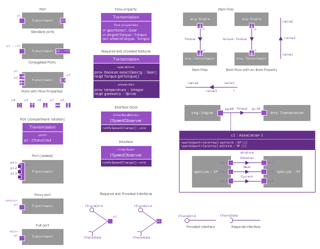
The vector stencils library "Ports and Flows" contains 26 SysML symbols.
Use it to design your SysML diagrams using ConceptDraw PRO diagramming and vector drawing software.
"The main motivation for specifying ports and flows is to enable design of modular, reusable blocks with clearly defined
ways of connecting and interacting with their context of use. This clause extends UML ports to support nested ports, and
extends blocks to support flow properties, and required and provided features, including blocks that type ports. Ports can be typed by blocks that support operations, receptions, and properties as in UML. SysML defines a specialized form of Block (InterfaceBlock) that can be used to support nested ports. SysML identifies two kinds of ports, one that exposes
features of the owning block or its internal parts (proxy ports), and another that supports its own features (full ports). Default compatibility rules are defined for connecting blocks used in composite structure, including parts and ports, with association blocks available to define more specific ways of doing this. These additional capabilities in SysML enable modelers to specify a wide variety of interconnectable components, which can be implemented through many engineering and social techniques, such as software, electrical or mechanical components, and human organizations. This clause also extends UML information flows for specifying item flows across connectors and associations." [www.omg.org/ spec/ SysML/ 1.3/ PDF]
The SysML shapes example "Design elements - Ports and Flows" is included in the SysML solution from the Software Development area of ConceptDraw Solution Park.
SysML ports and flows symbols
 Business Processes Area
Solutions of Business Processes area extend ConceptDraw PRO software with samples, templates and vector stencils libraries for drawing business process diagrams and flowcharts for business process management.
 Mathematics
Mathematics solution extends ConceptDraw PRO software with templates, samples and libraries of vector stencils for drawing the mathematical illustrations, diagrams and charts.
HelpDesk
How to Draw a Chemical Process Flow Diagram

 Picture Graphs
Typically, a Picture Graph has very broad usage. They many times used successfully in marketing, management, and manufacturing. The Picture Graphs Solution extends the capabilities of ConceptDraw PRO v10 with templates, samples, and a library of professionally developed vector stencils for designing Picture Graphs.
HelpDesk
How to Draw Physics Diagrams in ConceptDraw PRO
")
 Chemistry
This solution extends ConceptDraw PRO software with samples, template and libraries of vector stencils for drawing the Chemistry Illustrations for science and education.
 Cross-Functional Flowcharts
Cross-functional flowcharts are powerful and useful tool for visualizing and analyzing complex business processes which requires involvement of multiple people, teams or even departments. They let clearly represent a sequence of the process steps, the order of operations, relationships between processes and responsible functional units (such as departments or positions).
 Winter Sports
The Winter Sports solution from Sport area of ConceptDraw Solution Park contains winter sports illustration examples, templates and vector clipart libraries.
- Standard Symbols For Mechanical Diagrams
- Engineering | Mechanical Engineering | Universal Diagramming ...
- Mechanical Drawing Symbols | Mechanical Engineering ...
- Mechanical Drawing Symbols | Mechanical Engineering | Elements ...
- Mechanical Drawing Symbols | Design elements - Chemical ...
- Basic Flowchart Symbols | Flow Chart Symbols | Process Flowchart ...
- Engineering | Process Flowchart | Total Quality Management TQM ...
- Mechanical Drawing Symbols | Elements location of a welding ...
- Common joint types | Welded joints types | Butt weld geometry ...
- Mechanical Drawing Symbols | Mechanical Engineering | Technical ...
- Mechanical Engineering | Mechanical Drawing Symbols ...
- Mechanical Drawing Symbols | Mechanical Engineering | Design ...
- Mechanical Drawing Symbols | Mechanical Engineering ...
- Mechanical Drawing Symbols | Technical Drawing Software ...
- Mechanical Drawing Symbols | Elements location of a welding ...
- Mechanical Drawing Symbols | Elements location of a welding ...
- Mechanical Engineering Drawing Symbols Chart
- Mechanical Drawing Symbols | Mechanical Engineering ...
- Mechanical Drawing Symbols | Mechanical Engineering | Basic ...
- Elements location of a welding symbol | Mechanical Engineering ...