"The symbols and conventions used in welding documentation are specified in national and international standards such as ISO 2553 Welded, brazed and soldered joints -- Symbolic representation on drawings and ISO 4063 Welding and allied processes -- Nomenclature of processes and reference numbers. The US standard symbols are outlined by the American National Standards Institute and the American Welding Society and are noted as "ANSI/ AWS".
In engineering drawings, each weld is conventionally identified by an arrow which points to the joint to be welded. The arrow is annotated with letters, numbers and symbols which indicate the exact specification of the weld. In complex applications, such as those involving alloys other than mild steel, more information may be called for than can comfortably be indicated using the symbols alone. Annotations are used in these cases." [Symbols and conventions used in welding documentation. Wikipedia]
The example chart "Elements of welding symbol" is redesigned using the ConceptDraw PRO diagramming and vector drawing software from the Wikipedia file: Elements of a welding symbol.PNG.
[en.wikipedia.org/ wiki/ File:Elements_ of_ a_ welding_ symbol.PNG]
The diagram example "Elements location of a welding symbol" is contained in the Mechanical Engineering solution from the Engineering area of ConceptDraw Solution Park.
Welding joint symbol chart

Electrical Symbols, Electrical Diagram Symbols

Types of Welding in Flowchart

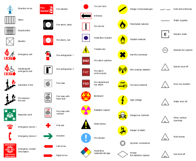
The design elements library "Fire and emergency planning" contains 58 fire safety symbols for developing the fire escape plans using the ConceptDraw PRO diagramming and vector drawing software.
The fire escape plan shows the location of fire alarm and extinguishing equipment, stairs and emergency exits, and evacuation orders and path.
"Hazard symbols are recognizable symbols designed to warn about hazardous materials, locations, or objects, including electric currents, poisons, and other things. The use of hazard symbols is often regulated by law and directed by standards organizations. Hazard symbols may appear with different colors, backgrounds, borders and supplemental information in order to specify the type of hazard." [Hazard symbol. Wikipedia]
The vector stencils library Fire and emergency planning is included in the Fire and Emergency Plans solution from the Building Plans" area of ConceptDraw Solution Park.
Safety symbols
Interior Design. Machines and Equipment — Design Elements

Electrical Symbols — Inductors

Mechanical Drawing Symbols

Electrical Symbols — Power Sources

Cisco Multimedia, Voice, Phone. Cisco icons, shapes, stencils and symbols

Technical Drawing Software

- Elements location of a welding symbol | Elements location of a ...
- Elements location of a welding symbol | Aws Vs Iso Welding
- Elements location of a welding symbol | Welding - Vector stencils ...
- Elements location of a welding symbol | Mechanical Drawing ...
- Elements location of a welding symbol | Welding symbols | Design ...
- Welding symbols | Elements location of a welding symbol | Design ...
- Elements location of a welding symbol | Design elements - Welding ...
- Elements location of a welding symbol | Design elements - Location ...
- Elements location of a welding symbol | Welding symbols | Elements ...
- Elements location of a welding symbol | Spatial infographics Design ...