 Office Layout Plans
Office layouts and office plans are a special category of building plans and are often an obligatory requirement for precise and correct construction, design and exploitation office premises and business buildings. Designers and architects strive to make office plans and office floor plans simple and accurate, but at the same time unique, elegant, creative, and even extraordinary to easily increase the effectiveness of the work while attracting a large number of clients.
The vector stencils library "Network layout floorplan" contain 34 symbol icons for drawing computer network floor plans, communication equipment layouts, and structured cabling diagrams.
"Structured cabling is building or campus telecommunications cabling infrastructure that consists of a number of standardized smaller elements (hence structured) called subsystems. ...
Structured cabling design and installation is governed by a set of standards that specify wiring data centers, offices, and apartment buildings for data or voice communications using various kinds of cable, most commonly category 5e (CAT-5e), category 6 (CAT-6), and fibre optic cabling and modular connectors. These standards define how to lay the cabling in various topologies in order to meet the needs of the customer, typically using a central patch panel (which is normally 19 inch rack-mounted), from where each modular connection can be used as needed. Each outlet is then patched into a network switch (normally also rack-mounted) for network use or into an IP or PBX (private branch exchange) telephone system patch panel." [Structured cabling. Wikipedia]
The design elements example "Network layout floorplan - Vector stencils library" was created using the ConceptDraw PRO diagramming and vector drawing software extended with the Network Layout Floor Plans solution from the Computer and Networks area of ConceptDraw Solution Park.
PC

Scanner

Switch

Router

Modem

Hub

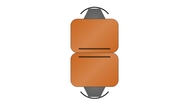
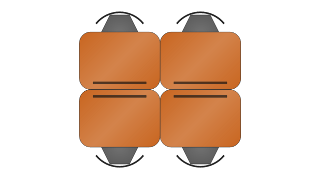
Rack Mount

Printer

Floor Mounted Outlet

Single Outlet

Duplex Outlet

Direct bus cable

Tops or bottoms bus cable

Side to side bus cable

Multi-tree bus cable

Bottom to side bus cable

Sides bus cable

Door

Door, threshold

Door, stop

Door, stop, threshold

Door, frame

Door, frame, threshold

Door, frame, stop

Door, frame, stop, threshold

Window

Window, sill

Window, sash

Window, sash, sill

Window, frame

Window, frame, sill

Window, frame, sash

Window, frame, sash, sill

Business diagrams & Org Charts with ConceptDraw DIAGRAM


 ConceptDraw Solution Park
ConceptDraw Solution Park collects graphic extensions, examples and learning materials
The vector stencils library "School layout" contains 19 symbols of school furniture and educational equipment. Use these shapes for drawing layout floor plans of school classrooms, universiry lecture halls and auditories, training offices in he ConceptDraw PRO diagramming and vector drawing software extended with the School and Training Plans solution from the Building Plans area of ConceptDraw Solution Park.
Single Desk

Double Desk

Student Desk

Student Desk - Group of 2
Student Desk - Group of 4
Lecture Hall Desk

Chair

Curved Back Chair
Teacher's Desk
Bookcase

Podium
Semi-circular Table

Chalkboard

Portable Chalkboard

Screen
Locker
Bank of 5 Lockers
Globe

Papers

Design Element: Rack Diagram for Network Diagrams
.png)

- Network Layout Floor Plans | Design elements - Network layout ...
- Network Layout Floor Plans | Network Layout | Design elements ...
- Network Layout Floor Plans | Ethernet local area network layout floor ...
- Network Layout Floor Plans | Design elements - Network layout ...
- Design elements - Network layout floorplan | Building Drawing ...
- Network Layout Floor Plans | Ethernet local area network layout floor ...
- Network Layout Floor Plans | Logical network topology diagram ...
- Office Layout Plans | Design elements - Outlets | Cafe electrical floor ...
- Network Layout Floor Plans | Network Layout | Office Layout Plans ...
- Network Layout Floor Plans | Cafe and Restaurant Floor Plan ...
- Interior Design Office Layout Plan Design Element | Design ...
- Office wireless network plan | Office Layout Plans | Examples of ...
- Network Layout Floor Plans | Network Layout | How to Create a ...
- Network Layout Floor Plans | Office Layout | Cafe and Restaurant ...
- Cafe and Restaurant Floor Plan
- Building Drawing Design Element: Office Layout Plan | Office Layout ...
- Interior Design Office Layout Plan Design Element | How To use ...
- Network Layout Floor Plans | Network Layout | Design elements ...
- Ethernet local area network layout floor plan | Network layout ...