Sequence Diagram Tool
Process Flowchart


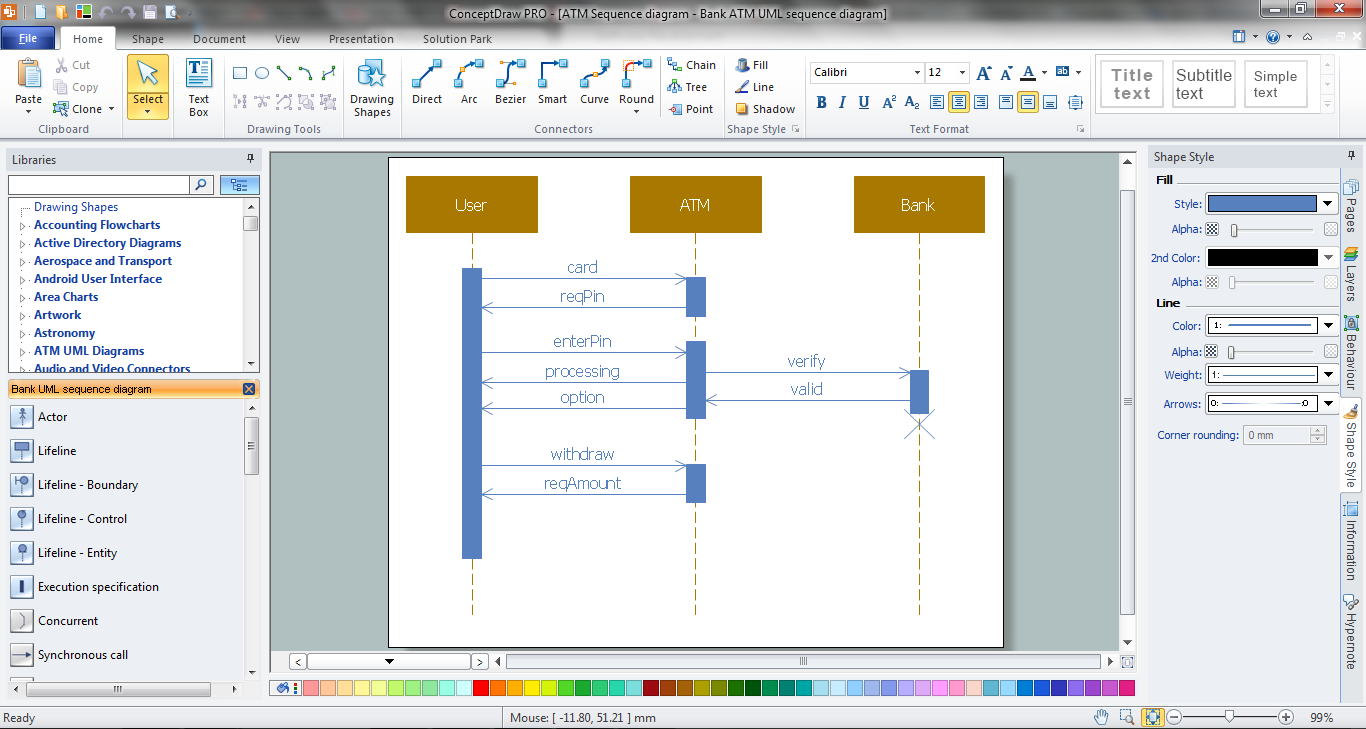
Bank Sequence Diagram
Timing diagram


IDEF1X Standard

ConceptDraw DIAGRAM ER Diagram Tool

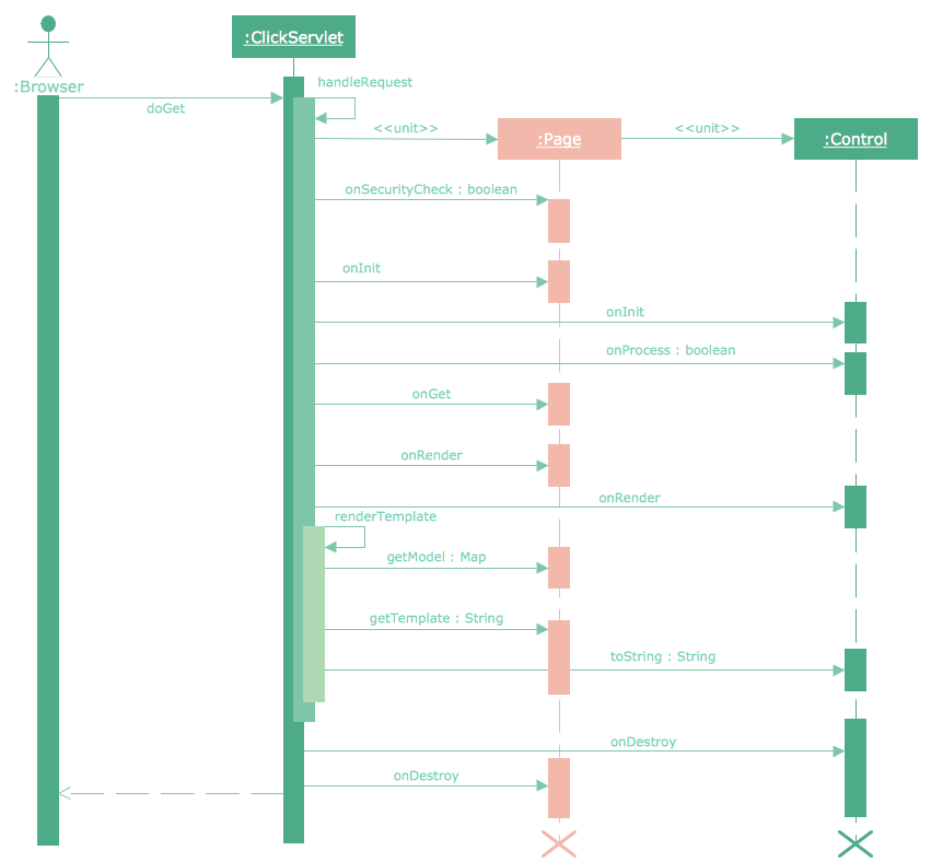
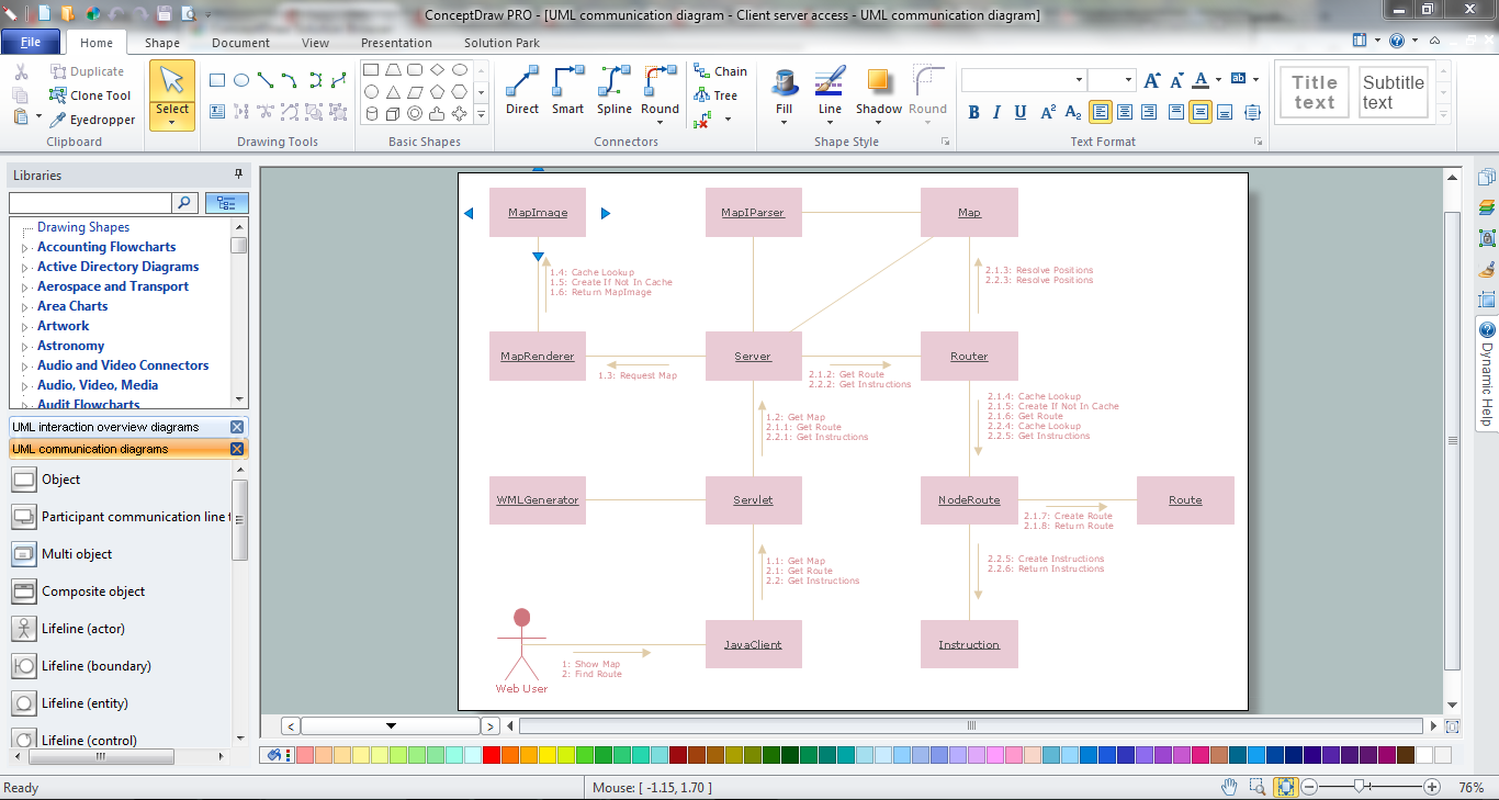
 ATM UML Diagrams
The ATM UML Diagrams solution lets you create ATM solutions and UML examples. Use ConceptDraw DIAGRAM as a UML diagram creator to visualize a banking system.
UML Class Diagram Generalization Example UML Diagrams

Online Diagram Tool
Cloud Computing Architecture Diagrams

- Draw A Sequence Diagram Of Atm In Microsoft Visio
- Bank Sequence Diagram | ATM UML Diagrams | Bank ATM use ...
- ATM UML Diagrams | Audit Flowcharts | Draw Sequence Diagram ...
- UML Sequence Diagram | UML Deployment Diagram Example ...
- UML Sequence Diagram | Bank Sequence Diagram | UML Diagram ...
- Diagramming Software for designing UML Sequence Diagrams ...
- ATM Sequence diagram | UML activity diagram - Cash withdrawal ...
- ATM UML Diagrams | PM Dashboards | SYSML | Sequence ...
- Rapid UML | ATM UML Diagrams | UML sequence diagram ...
- Bank Sequence Diagram | UML use case diagram - Banking system ...