How To use House Electrical Plan Software


How To use Switches in Network Diagram


Network wiring cable. Computer and Network Examples

Local area network (LAN). Computer and Network Examples
 diagram")
This cafe electrical floor plan sample shows the outlet and switch layout.
"An electrical drawing, is a type of technical drawing that shows information about power, lighting, and communication for an engineering or architectural project. Any electrical working drawing consists of "lines, symbols, dimensions, and notations to accurately convey an engineering's design to the workers, who install the electrical system on the job".
A complete set of working drawings for the average electrical system in large projects usually consists of:
(1) A plot plan showing the building's location and outside electrical wiring.
(2) Floor plans showing the location of electrical systems on every floor.
(3) Power-riser diagrams showing panel boards.
(4) Control wiring diagrams.
(5) Schedules and other information in combination with construction drawings.
Electrical drafters prepare wiring and layout diagrams used by workers who erect, install, and repair electrical equipment and wiring in communication centers, power plants, electrical distribution systems, and buildings." [Electrical drawing. Wikipedia]
The outlet and switch layout example "Cafe electrical floor plan" was created using the ConceptDraw PRO diagramming and vector drawing software extended with the Electric and Telecom Plans solution from the Building Plans area of ConceptDraw Solution Park.
Outlet and switch layout

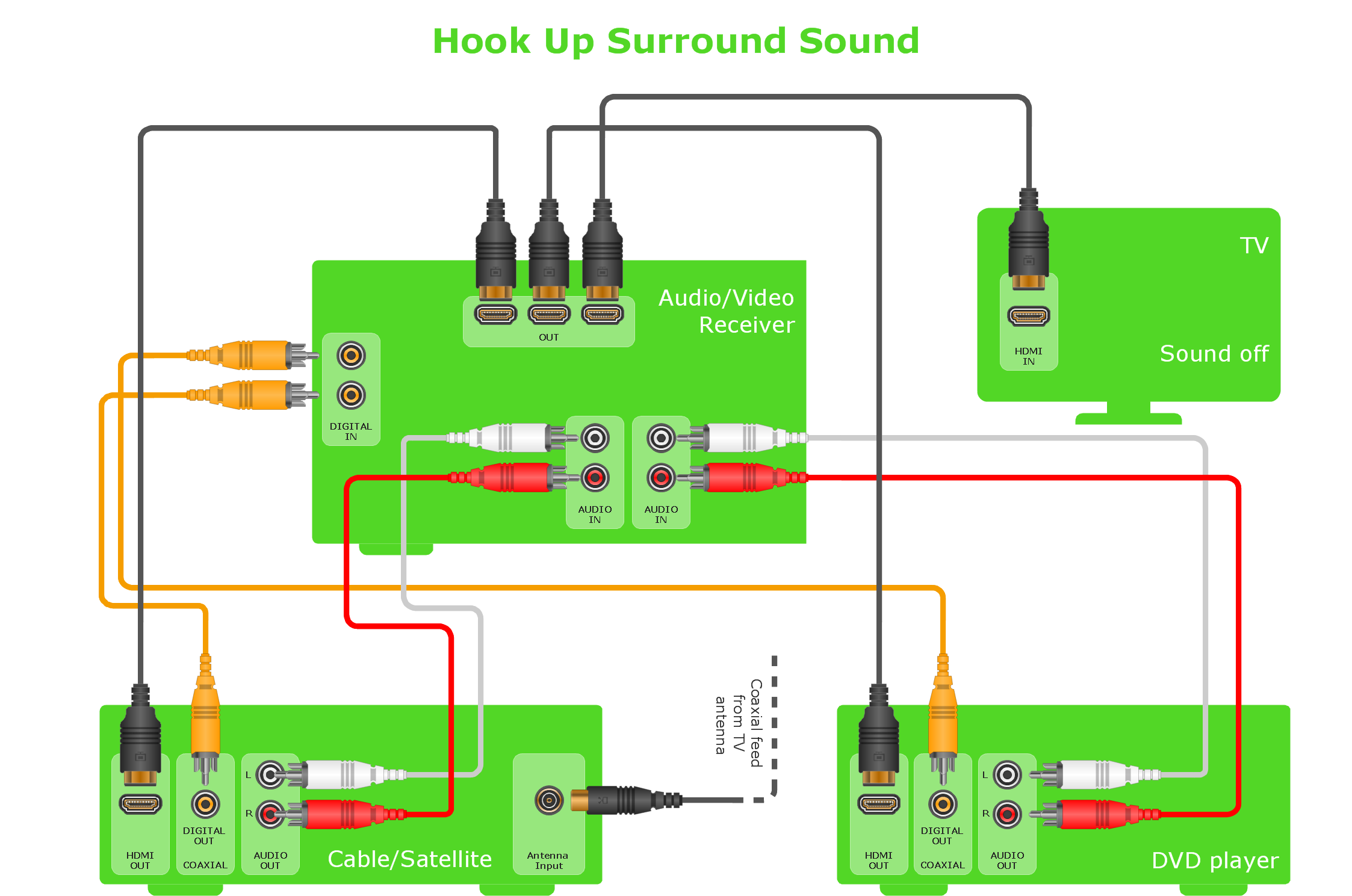
Audio & Video Connector Types
Electrical Symbols, Electrical Diagram Symbols

Basic Network Diagram

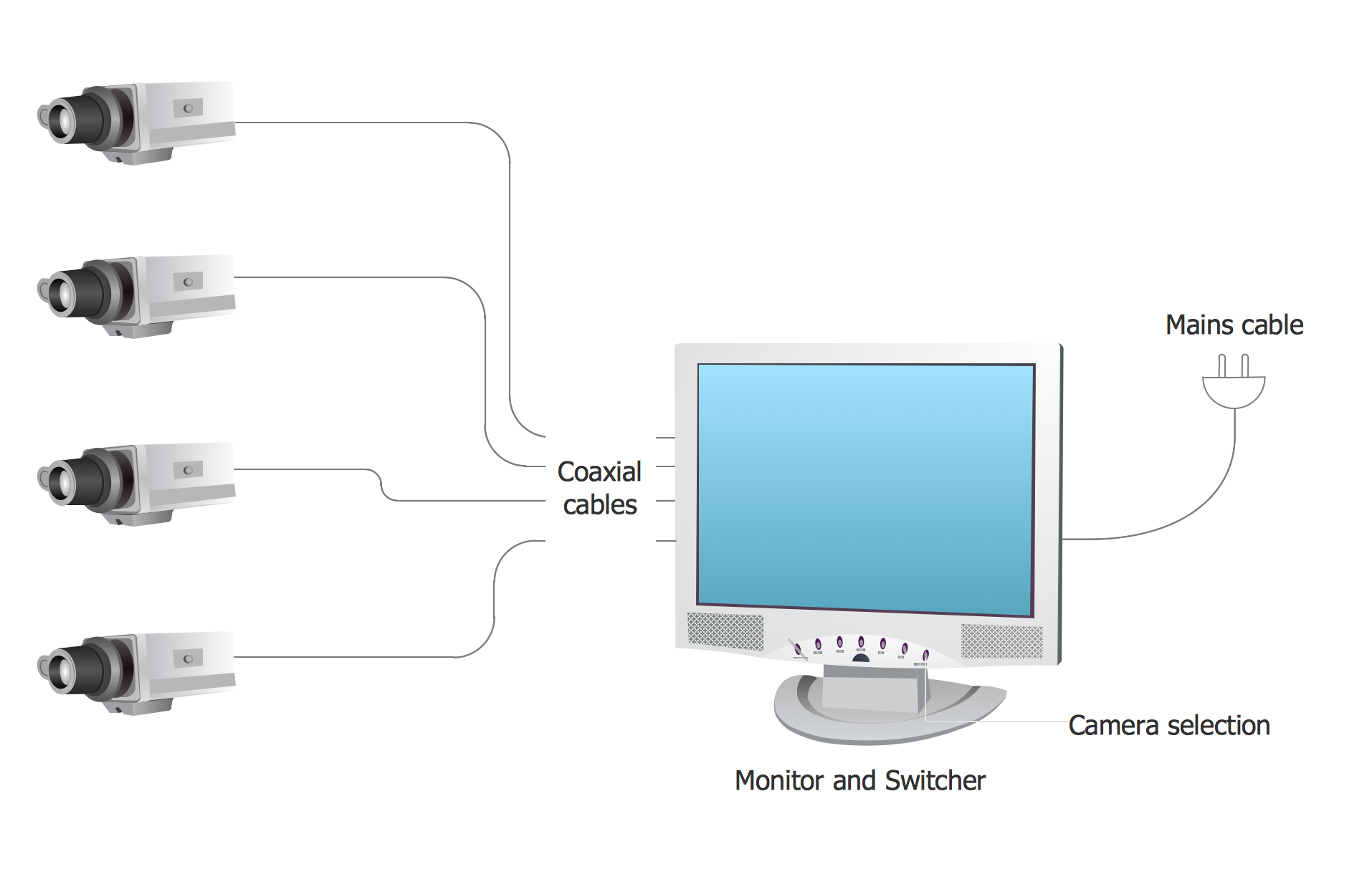
Basic CCTV System Diagram. CCTV Network Diagram Example
Wiring Diagrams with ConceptDraw DIAGRAM

- Cafe electrical floor plan | Restaurant Floor Plans Samples | How To ...
- Electrical Layout Riser Diagram Sample
- Lighting and switch layout | Design elements - Electrical and ...
- Banquet Hall Plan Software | UML Use Case Diagram Example ...
- Audio and Video Connections Explained | Basic Diagramming | How ...
- Draw And Explain The Layout Electrical Power System
- Riser Diagram Electrical Sample
- CCTV Surveillance System Diagram. CCTV Network Diagram ...
- Cafe electrical floor plan | Design elements - Qualifying | Design ...
- Basic Elements Of Telecommunication System