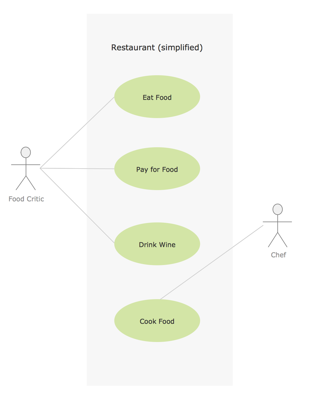
Jacobson Use Cases Diagram

This SysML diagram example was redesigned from Wikimedia Commons file: Use case restaurant model.svg.
"Use case model of a restaurant business." [commons.wikimedia.org/ wiki/ File:Use_ case_ restaurant_ model.svg]
"The use case diagram describes the usage of a system (subject) by its actors (environment) to achieve a goal, that is
realized by the subject providing a set of services to selected actors. The use case can also be viewed as functionality and/
or capabilities that are accomplished through the interaction between the subject and its actors. Use case diagrams include the use case and actors and the associated communications between them. Actors represent classifier roles that are external to the system that may correspond to users, systems, and or other environmental entities. They may interact either directly or indirectly with the system. The actors are often specialized to represent a taxonomy of user types or external systems." [omg.org/ spec/ SysML/ 1.3/ ]
The SysML diagram example "Use case restaurant model" was drawn using the ConceptDraw PRO diagramming and vector drawing software extended with the SysML solution from the Software Development area of ConceptDraw Solution Park.
Example of SysML use case diagram

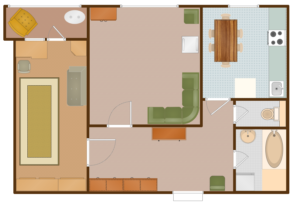
 Cafe and Restaurant Floor Plans
Restaurants and cafes are popular places for recreation, relaxation, and are the scene for many impressions and memories, so their construction and design requires special attention. Restaurants must to be projected and constructed to be comfortable and e
Model Based Systems Engineering

UML Class Diagram Example - Buildings and Rooms

HelpDesk
How to Create a Bank ATM Use Case Diagram

Sample for UML
Systems Engineering

Design Elements for UML Diagrams

UML Diagram Types List

Floor Plan

Banquet Hall Plan Software

 Event-driven Process Chain Diagrams
Event-Driven Process Chain Diagrams solution extends ConceptDraw DIAGRAM functionality with event driven process chain templates, samples of EPC engineering and modeling the business processes, and a vector shape library for drawing the EPC diagrams and EPC flowcharts of any complexity. It is one of EPC IT solutions that assist the marketing experts, business specialists, engineers, educators and researchers in resources planning and improving the business processes using the EPC flowchart or EPC diagram. Use the EPC solutions tools to construct the chain of events and functions, to illustrate the structure of a business process control flow, to describe people and tasks for execution the business processes, to identify the inefficient businesses processes and measures required to make them efficient.
- Jacobson Use Cases Diagram | UML Business Process | Use case ...
- Jacobson Use Cases Diagram | Use case restaurant model | UML ...
- Jacobson Use Cases Diagram | Use case restaurant model | Cafe ...
- Jacobson Use Cases Diagram | Use case restaurant model ...
- Jacobson Use Cases Diagram | Use case restaurant model | How to ...
- Use case restaurant model
- Jacobson Use Cases Diagram | Cafe and Restaurant Floor Plan ...
- Entity-Relationship Diagram (ERD) | Use case restaurant model ...
- Use Case Diagrams Restaurant Management System Actors
- Jacobson Use Cases Diagram | Cafe and Restaurant Floor Plan ...
- How To Create Restaurant Floor Plan in Minutes | Jacobson Use ...
- Cafe and Restaurant Floor Plan | Jacobson Use Cases Diagram ...
- Cafe and Restaurant Floor Plan | Dfd Dan Use Case Diagram Bank
- Simple Use Case Diagram Of Restaurant Management System Of
- Design A Use Case Diagram For Restaurant
- Use Case Diagram For Restaurant Management
- Restaurant For Use Case Diagram And Data Flow Diagram
- Use Case Diagram For Online Restaurant System
- Use Case Diagram For Online Restaurant
- Jacobson Use Cases Diagram | How to Create a Bank ATM Use ...