UML Flowchart Symbols
The UML diagram is a powerful tool which lets visually represent all system's components, the interactions between them and relationships with external user interface. The Rapid UML solution for ConceptDraw DIAGRAM software offers diversity of UML flowchart symbols for drawing all types of UML diagrams.SysML
Systems Modeling Language (SysML) is a general-purpose modeling language for systems engineering applications. ConceptDraw DIAGRAM diagramming and vector drawing software was extended with SysML Solution from the Software Development Area of ConceptDraw Solution Park specially to help systems engineers design various model systems with SysML.Personal area (PAN) networks. Computer and Network Examples
Personal area network (PAN) is a network organized on a limited area and used for data transmission between various personal devices, such as computers, tablets, laptops, telephones, different digital and mobile devices, etc. and also for connecting to higher level network and Internet. PAN is used to manage the interconnections of IT devices which surround a single user and generally contains such appliances, as cordless mice, keyboard, phone, and Bluetooth handsets. PANs can be wired with computer buses, or wirelessly connected to the Internet using such network technologies as Bluetooth, Z-Wave, ZigBee, IrDa, UWB, Body Area Network. PANs have a lot of pros and cons, they are expedient, lucrative and handy, but sometimes have bad connection with other networks on the same radio bands, Bluetooth has distance limits and slow data transfer speed, but is comparatively safe. ConceptDraw DIAGRAM diagramming software supplied with numerous solutions of Computer and Networks Area included to ConceptDraw Solution Park perfectly suits for designing the Personal Area Networks.
Model Based Systems Engineering
ConceptDraw DIAGRAM is a professional diagramming and vector drawing software. Now, enhanced with SysML Solution from the Software Development Area of ConceptDraw Solution Park, ConceptDraw DIAGRAM became an ideal software for model based systems engineering (MBSE).
 ConceptDraw Solution Park
ConceptDraw Solution Park collects graphic extensions, examples and learning materials
HelpDesk
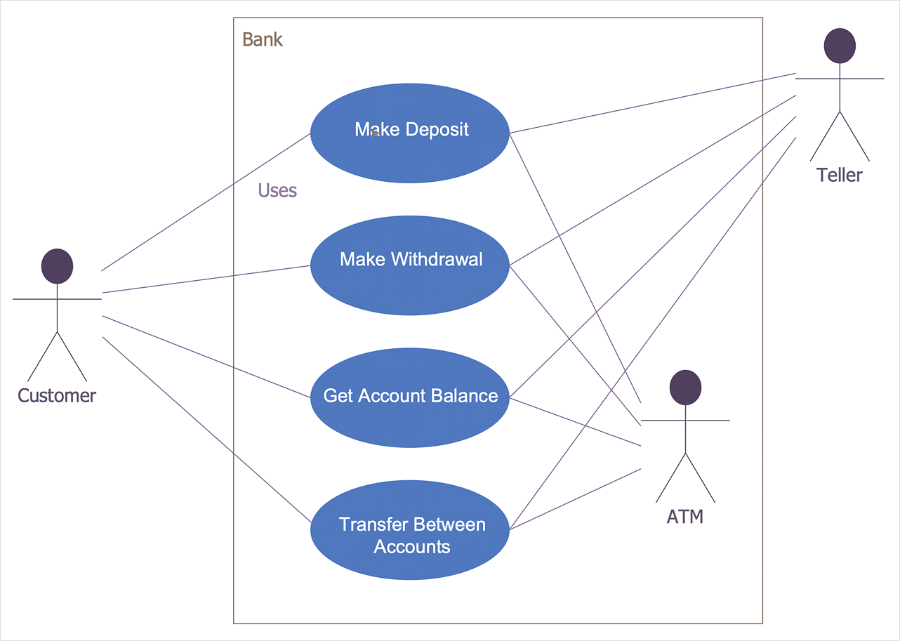
How to Create a Bank ATM Use Case Diagram
UML diagrams are often used in banking management for documenting a banking system. In particular, the interaction of bank customers with an automated teller machine (ATM) can be represented in a Use Case diagram. Before the software code for an ATM, or any other system design, is written, it is necessary to create a visual representation of any object-oriented processes. This is done most effectively by creating a Unified Modeling Language (UML) diagram, using object-oriented modeling. UML works as a general purpose modeling language for software engineers or system analysts, offering a number of different diagram styles with which to visually depict all aspects of a software system. ConceptDraw DIAGRAM diagramming software, enhanced and expanded with the ATM UML Diagrams solution, offers the full range of icons, templates and design elements needed to faithfully represent ATM and banking information system architecture using UML standards. The ATM UML Diagrams solution is useful for beginner and advanced users alike. More experienced users will appreciate a full range of vector stencil libraries and ConceptDraw DIAGRAM 's powerful software, that allows you to create your ATM UML diagram in a matter of moments.Systems Engineering
Systems engineering is an interdisciplinary field of engineering that focuses on how to design and manage complex engineering systems over their life cycles. ConceptDraw DIAGRAM supplied with SysML Solution from the Software Development Area of ConceptDraw Solution Park is a powerful and effective systems engineering software.- Technical Drawing Software | Process Flowchart | How To Create ...
- SysML Diagram | Process Flowchart | SysML | Diagram Software ...
- SysML Diagram | SysML | Process Flowchart | Open Source Uml ...
- Business diagrams & Org Charts with ConceptDraw PRO | Example ...
- Data Flow Diagram Symbols. DFD Library | Dimensioning and ...
- Mechanical Drawing Symbols | Design elements - Dimensioning ...
- Multi Layer Venn Diagram. Venn Diagram Example | Diagramming ...
- Mechanical Engineering | Mechanical Drawing Software | Technical ...
- How to Create a Seating Chart for Wedding or Event | Examples of ...
- Basic Flowchart Symbols and Meaning | Process Flowchart | How to ...
- UML Use Case Diagram Example. Services UML Diagram. ATM ...
- Mechanical Drawing Symbols | Design elements - Dimensioning ...
- Design elements - Dimensioning and tolerancing | Dimensioning ...
- Basic Flowchart Symbols and Meaning | Contoh Flowchart | Sales ...
- UML package diagram - Template | UML Deployment Diagram ...
- Basic Flowchart Symbols and Meaning | Process Flowchart ...
- Store Layout Software | Example of DFD for Online Store (Data Flow ...
- Elements location of a welding symbol | Mechanical Engineering ...
- How to Present Workflow to Team | How to Draw a Good Diagram of ...
- Workflow Diagram Template | Workflow diagrams - Vector stencils ...


