This electrical floot plan sample shows the Power socket outlet layout.
"The term plug is in general and technical use in all forms of English, common alternatives being power plug, electric plug, and (in the UK) plug top. The normal technical term (in both British and International English) for an AC power socket is socket-outlet, but in non-technical common use a number of other terms are used. In British English the general term is socket, but there are numerous common alternatives, including power point, plug socket, wall socket, and wall plug. In American English receptacle and outlet are common, sometimes with qualifiers such as wall outlet, electrical outlet and electrical receptacle, all of these sometimes to be found in the same document. A socket may be surrounded by a decorative and/ or protective cover called a wall plate, face plate, outlet cover, socket cover, or wall cover. In some designs this is an integral piece with the socket itself, bought and installed as a single unit." [AC power plugs and sockets. Wikipedia]
The electrical floot plan example "Power socket outlet layout" was created using the ConceptDraw PRO diagramming and vector drawing software extended with the Electric and Telecom Plans solution from the Building plans area of ConceptDraw Solution Park.
Electrical floot plan

How To use House Electrical Plan Software


Electrical Symbols, Electrical Diagram Symbols

The vector stenvils library "Outlets" contains 57 symbols of electrical outlets.
Use these shapes for drawing building interior design, electrical floor plans and layouts of AC power plugs and sockets in the ConceptDraw PRO diagramming and vector drawing software.
The vector stencils library "Outlets" is included in the Electric and Telecom Plans solution from the Building Plans area of ConceptDraw Solution Park.
Single Outlet

Single Outlet and Switch

Emergency Circuit Single Outlet

Duplex Convenience Outlet

Emergency Circuit Duplex Outlet

Weatherproof Convenience Outlet

Range Outlet

Switch and Convenience Outlet

Radio and Convenience Outlet

Radio Outlet

Dedicated Duplex Outlet

Duplex Ground Fault Interrupter

Split Wired Duplex Outlet

240v Outlet

Floor Mounted Outlet

Floor Special-purpose Outlet

Heavy Duty Outlet

Heavy Duty Outlet with Convenience Outlet

Triplex Outlet

Split Wired Triplex Outlet

Quadruplex Outlet

Emergency Circuit Quadruplex Outlet

Special-purpose Outlet

Duplex Special-purpose Outlet

Special-purpose connection or provision for connection

Multi-outlet Assembly

Data/voice, Power Floor Mounted Outlet

Clock Hanger Outlet, Mounted

Blanked Outlet

Drop Outlet

Electrical Outlet

Fan Outlet

Junction Box

Lamp Holder

Lamp holder with pull switch

Pull Switch

Vapor discharge lamp outlet

Exit Light Outlet

Floor Receptacle

Telephone outlet

Floor Phone Outlet

Wall Phone Outlet

Weatherproof Phone Outlet

Phone Feed

Computer Data Outlet

Television outlet

Floor TV Outlet

TV Feed

Weatherproof TV Outlet

TV and Phone Outlet

Door Phone Outlet

Fax Outlet

Fiber Outlet

Multi-Purpose Outlet

Local Area Network Outlet

Wall Mounted Data Outlet

Wall Mounted Data/Telephone Outlet

Building Drawing Software for Design Office Layout Plan


Electrical Symbols — Terminals and Connectors

"The Ethernet physical layer is the physical layer component of the Ethernet family of computer network standards.
The Ethernet physical layer evolved over a considerable time span and encompasses quite a few physical media interfaces and several magnitudes of speed. The speed ranges from 1 Mbit/ s to 100 Gbit/ s, while the physical medium can range from bulky coaxial cable to twisted pair and optical fiber. In general, network protocol stack software will work similarly on all physical layers.
10-gigabit Ethernet was already used in both enterprise and carrier networks by 2007, with 40 Gbit/ s and 100 Gbit/ s Ethernet ratified. ...
Many Ethernet adapters and switch ports support multiple speeds, using autonegotiation to set the speed and duplex for the best values supported by both connected devices. If auto-negotiation fails, a multiple-speed device will sense the speed used by its partner, but will assume half-duplex. A 10/ 100 Ethernet port supports 10BASE-T and 100BASE-TX. A 10/ 100/ 1000 Ethernet port supports 10BASE-T, 100BASE-TX, and 1000BASE-T." [Ethernet physical layer. Wikipedia]
The LAN equipment and cabling layout floorplan example "Ethernet local area network layout floor plan" was created using the ConceptDraw PRO diagramming and vector drawing software extended with the Network Layout Floor Plans solution from the Computer and Networks area of ConceptDraw Solution Park.
Ethernet LAN layout floorplan

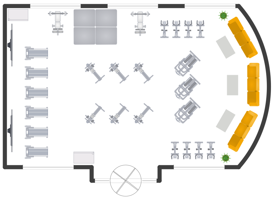
Gym Layout
The vector stenvils library "Outlets" contains 57 symbols of electrical outlets.
Use these shapes for drawing building interior design, electrical floor plans and layouts of AC power plugs and sockets in the ConceptDraw PRO diagramming and vector drawing software.
The vector stencils library "Outlets" is included in the Electric and Telecom Plans solution from the Building Plans area of ConceptDraw Solution Park.
Use these shapes for drawing building interior design, electrical floor plans and layouts of AC power plugs and sockets in the ConceptDraw PRO diagramming and vector drawing software.
The vector stencils library "Outlets" is included in the Electric and Telecom Plans solution from the Building Plans area of ConceptDraw Solution Park.
Single Outlet
Single Outlet and Switch
Emergency Circuit Single Outlet
Duplex Convenience Outlet
Emergency Circuit Duplex Outlet
Weatherproof Convenience Outlet
Range Outlet
Switch and Convenience Outlet
Radio and Convenience Outlet
Radio Outlet
Dedicated Duplex Outlet
Duplex Ground Fault Interrupter
Split Wired Duplex Outlet
240v Outlet
Floor Mounted Outlet
Floor Special-purpose Outlet
Heavy Duty Outlet
Heavy Duty Outlet with Convenience Outlet
Triplex Outlet
Split Wired Triplex Outlet
Quadruplex Outlet
Emergency Circuit Quadruplex Outlet
Special-purpose Outlet
Duplex Special-purpose Outlet
Special-purpose connection or provision for connection
Multi-outlet Assembly
Data/voice, Power Floor Mounted Outlet
Clock Hanger Outlet, Mounted
Blanked Outlet
Drop Outlet
Electrical Outlet
Fan Outlet
Junction Box
Lamp Holder
Lamp holder with pull switch
Pull Switch
Vapor discharge lamp outlet
Exit Light Outlet
Floor Receptacle
Telephone outlet
Floor Phone Outlet
Wall Phone Outlet
Weatherproof Phone Outlet
Phone Feed
Computer Data Outlet
Television outlet
Floor TV Outlet
TV Feed
Weatherproof TV Outlet
TV and Phone Outlet
Door Phone Outlet
Fax Outlet
Fiber Outlet
Multi-Purpose Outlet
Local Area Network Outlet
Wall Mounted Data Outlet
Wall Mounted Data/Telephone Outlet
- Power socket outlet layout | Network Layout Floor Plans | Power ...
- Power socket outlet layout | Cafe electrical floor plan | Network ...
- Power socket outlet layout
- Power socket outlet layout | Plant Layout Plans | Cafe electrical floor ...
- Power socket outlet layout | British Symbol For Double Socket
- Power socket outlet layout | Cafe electrical floor plan | Design ...
- Outlets - Vector stenvils library | Power socket outlet layout | Symbol ...
- Lighting and switch layout | Power socket outlet layout | Cafe ...
- Ethernet local area network layout floor plan | Outlets - Vector ...
- Power socket outlet layout | Design elements - Outlets | Electrical ...