The vector stencils library "Valves" contains 91 symbols of piping and plumbing valves.
"A valve is a device that regulates, directs or controls the flow of a fluid (gases, liquids, fluidized solids, or slurries) by opening, closing, or partially obstructing various passageways. Valves are technically valves fittings, but are usually discussed as a separate category. In an open valve, fluid flows in a direction from higher pressure to lower pressure.
The simplest, and very ancient, valve is simply a freely hinged flap which drops to obstruct fluid (gas or liquid) flow in one direction, but is pushed open by flow in the opposite direction. This is called a check valve, as it prevents or "checks" the flow in one direction.
People in developed nations use valves in their daily lives, including plumbing valves, such as taps for tap water, gas control valves on cookers, small valves fitted to washing machines and dishwashers, safety devices fitted to hot water systems..." [Valve. Wikipedia]
Use the design elements library "Valves" to draw building plans, schematic diagrams, blueprints, or technical drawings of industrial piping systems; process, vacuum, and fluids piping; hydraulics piping; air and gas piping; materials distribution; and liquid transfer systems using the ConceptDraw PRO diagramming and vector drawing software.
The shapes library "Valves" is included in the Plumbing and Piping Plans solution from the Building Plans area of ConceptDraw Solution Park.
Valve symbols

The vector stencils library "Valves" contains 91 symbols of valves. Use it for drawing plumbing and piping plans, schematic diagrams and blueprints of industrial piping systems; process, vacuum, and fluids piping; hydraulics piping; air and gas piping; materials distribution; and liquid transfer systems in the ConceptDraw PRO diagramming and vector drawing software extended with the Plumbing and Piping Plans solution from the Building Plans area of ConceptDraw Solution Park.
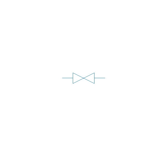
In-line valve

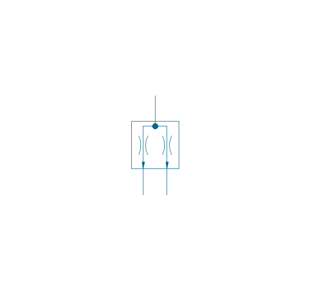
3-way valve

4-way valve

Screw-down valve

Lock-shield valve

Reel valve

Relief valve

Relief valve 2

Relief valve 3

Relief valve 4

Angle valve

Angle valve 2

Angle valve 3

Angle valve 4

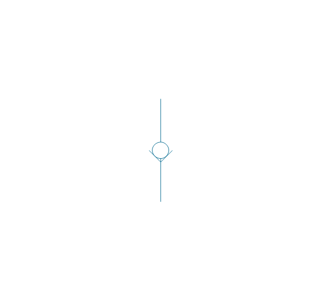
Check valve

Check valve 2

Screwdown valve

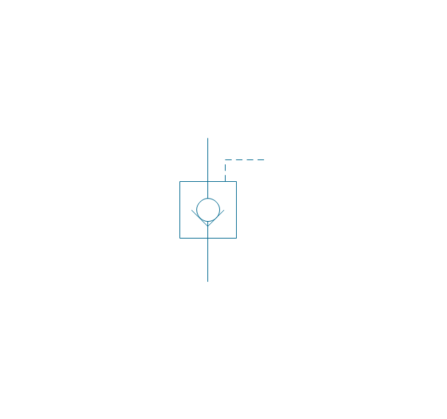
Float operated valve

Float operated valve 2

Flanged valve

Flanged valve 2

Butterfly valve

Butterfly valve 2

Globe valve

Globe valve 2

Globe valve 3

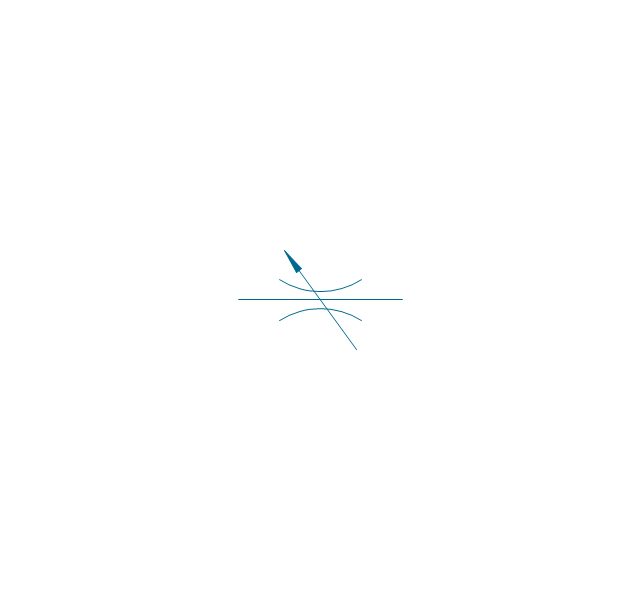
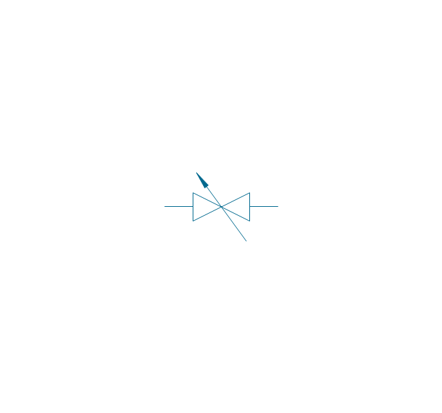
Needle valve

Needle valve 2

Needle valve 3

Needle valve 4

Diaphragm valve

Diaphragm valve 2

Diaphragm valve 3

Wedge gate valve

Parallel side valve

Gate valve

Ball valve

Ball valve 2

Ball valve 3

Powered control valve

Powered control valve 2

Powered control valve 3

Relief angle valve, pressure

Relief angle valve, vacuum

Reducing valve

Reducing valve 2

Plug valve

Plug valve 2

Plug valve, straight through

3-way plug valve

Plug valve, T-port

Plug valve, L-port

3-way plug valve

3-way plug valve 2

3-way plug valve 3

3-way plug valve, T-port

3-way plug valve, L-port

Mixing valve

Characterized port valve

Manual isolation

Power signal

Statically loaded

Spring loaded

Spring loaded 2

Remote control

Diaphragm

Diaphragm, positioner

Chain operated

Gear operated

Solenoid

Weight loaded

Weight loaded 2

Weight loaded 3

Float operated

Float operated 2

Dash-pot

Dash-pot 2

Piston

Quick opening

Quick opening 2

Quick closing

Quick closing 2

Connecting unit

Connecting unit 2

Connecting unit 3

Motor element

Motor element, opens on failure

Motor element, closes on failure

Motor element, retains position on fail

Motor element, safe direction

Regulating

The vector stencils library "Valves and fittings" contains 104 symbols of valve components.
Use these icons for drawing industrial piping systems; process, vacuum, and fluids piping; hydraulics piping; air and gas piping; materials distribution; and liquid transfer systems in the ConceptDraw PRO software extended with the Chemical and Process Engineering solution from the Chemical and Process Engineering area of ConceptDraw Solution Park.
www.conceptdraw.com/ solution-park/ engineering-chemical-process
Electrically bonded

Bursting disc

Flame arrester

Strainer

Separator

Exhaust silencer

Bell mouth

Exhaust head

Hydrant

Drain silencer

Liquid seal open/closed

Y strainer

Gate valve

Globe valve

Globe valve 2

Globe valve 3

Screw-down valve

Lock-shield valve

Reel valve

Check valve

Check valve 2

Check valve 3

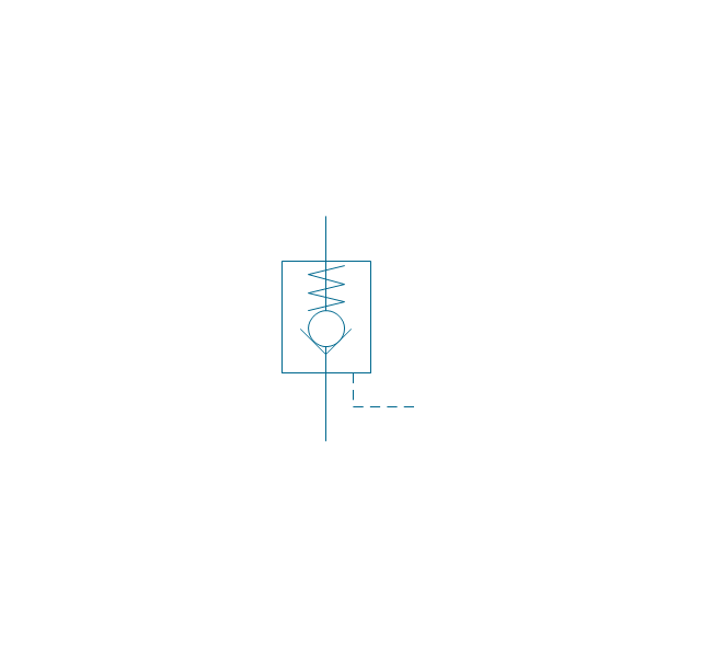
Screw-down check valve

Stop check valve

Diaphragm valve

Diaphragm valve 2

Diaphragm valve 3

Powered valve

Powered valve 2

Powered valve 3

Needle valve

Needle valve 2

Needle valve 3

Relief valve

Relief valve 2

Relief valve 3

Angle valve

Angle valve 2

Angle valve 3

Angle valve 4

Float operated valve

Float operated valve 2

Flanged valve

Butterfly valve

Butterfly valve 2

Wedge gate valve

Parallel slide valve

Ball valve

Ball valve 2

Ball valve 3

Relief angle valve vacuum

Relief angle valve pressure

Reducing valve

Reducing valve 2

Plug valve 3 way

Plug valve L point

Plug valve 2

Plug valve

Plug valve straight through

Plug valve T point

3-way plug valve

3-way plug valve 2

3-way plug valve 3

Mixing valve

Valve Manifold

Characterized port valve

Reducer

Reducer 2

General joint

Butt weld

Butt weld 2

Butt weld 3

Butt weld 4

Flanged/ bolted

Soldered / solvent

Soldered / solvent 2

Screwed joint

Screwed joint 2

Screwed joint 3

Socket and spigot

Socket and spigot 2

Socket and spigot 3

Sleeve

Sleeve 2

Screwed sleeve

Screwed sleeve 2

Socket weld

Socket weld 2

Swivel joint

Swivel joint 2

Swivel joint 3

End cap

End cap butt welded

End cap screwed

End cap socket and spigot

End cap fillet welded

End cap screwed and plugged

End cap quick release

End cap flanged and bolted

End cap flanged and bolted 2

Electrically insulated

Tundish

Syphon drain

Open vent

The vector stencils library "Valves and fittings" contains 104 symbols of valve components.
Use these icons for drawing industrial piping systems; process, vacuum, and fluids piping; hydraulics piping; air and gas piping; materials distribution; and liquid transfer systems.
"A valve is a device that regulates, directs or controls the flow of a fluid (gases, liquids, fluidized solids, or slurries) by opening, closing, or partially obstructing various passageways. Valves are technically valves fittings, but are usually discussed as a separate category. In an open valve, fluid flows in a direction from higher pressure to lower pressure.
The simplest, and very ancient, valve is simply a freely hinged flap which drops to obstruct fluid (gas or liquid) flow in one direction, but is pushed open by flow in the opposite direction. This is called a check valve, as it prevents or "checks" the flow in one direction. ...
Valves are found in virtually every industrial process, including water & sewage processing, mining, power generation, processing of oil, gas & petroleum, food manufacturing, chemical & plastic manufacturing and many other fields. ...
Valves may be operated manually, either by a handle, lever, pedal or wheel. Valves may also be automatic, driven by changes in pressure, temperature, or flow. These changes may act upon a diaphragm or a piston which in turn activates the valve, examples of this type of valve found commonly are safety valves fitted to hot water systems or boilers.
More complex control systems using valves requiring automatic control based on an external input (i.e., regulating flow through a pipe to a changing set point) require an actuator. An actuator will stroke the valve depending on its input and set-up, allowing the valve to be positioned accurately, and allowing control over a variety of requirements." [Valve. Wikipedia]
The example "Design elements - Valves and fittings" was created using the ConceptDraw PRO diagramming and vector drawing software extended with the Chemical and Process Engineering solution from the Engineering area of ConceptDraw Solution Park.
Valves and fittings symbols

Piping and Instrumentation Diagram Software

Building Drawing Software for Designing Plumbing


"A piping and instrumentation diagram/ drawing (P&ID) is a diagram in the process industry which shows the piping of the process flow together with the installed equipment and instrumentation. ...
P&IDs play a significant role in the maintenance and modification of the process that it describes. It is critical to demonstrate the physical sequence of equipment and systems, as well as how these systems connect. During the design stage, the diagram also provides the basis for the development of system control schemes, allowing for further safety and operational investigations, such as a Hazard Analysis and Operability Study...
For processing facilities, it is a pictorial representation of:
Key piping and instrument details,
Control and shutdown schemes,
Safety and regulatory requirements,
Basic start up and operational information." [Piping and instrumentation diagram. Wikipedia]
The piping and instrumentation diagram template for the ConceptDraw PRO diagramming and vector drawing software is included in the Chemical and Process Engineering solution from the Engineering area of ConceptDraw Solution Park.
Piping and instrumentation diagram / drawing (P&ID)
-piping-and-instrumentation-diagram-template.png--diagram-flowchart-example.png)
Electrical Diagram Symbols F.A.Q.How to Use Electrical ConceptDraw Diagram Software

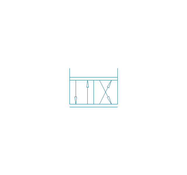
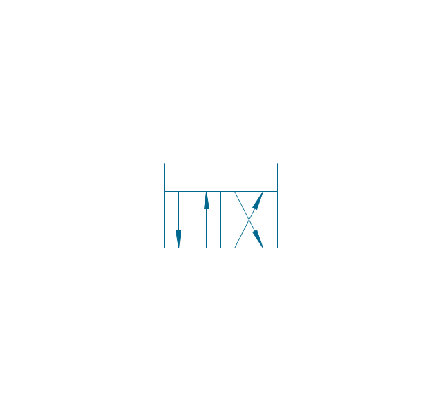
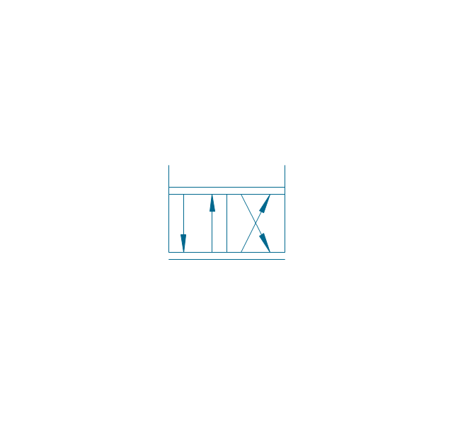
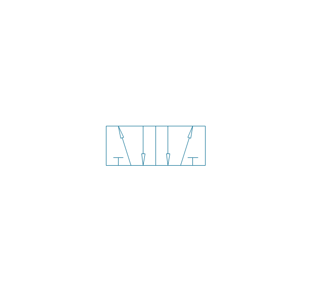
The vector stencils library "Fluid power valves" contains 93 symbols of pre-made hydraulic and pneumatic valves, including directional control valves, flow control valves, pressure control valves, and electrohydraulic and electropneumatic valves.
Use these shapes to design fluid power diagrams in the ConceptDraw PRO diagramming and vector drawing software extended with the Mechanical Engineering solution from the Engineering area of ConceptDraw Solution Park.
www.conceptdraw.com/ solution-park/ engineering-mechanical
Use these shapes to design fluid power diagrams in the ConceptDraw PRO diagramming and vector drawing software extended with the Mechanical Engineering solution from the Engineering area of ConceptDraw Solution Park.
www.conceptdraw.com/ solution-park/ engineering-mechanical
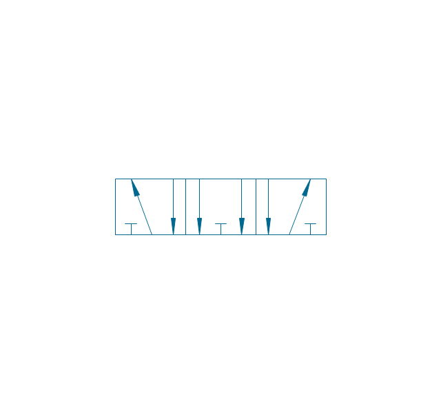
2/2 valve, pneum., finite positions

2/2 valve, pneum., infinite positions
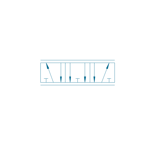
2/2 valve, pneum., ext., fin. pos.
2/2 valve, pneum., ext., infin. pos.
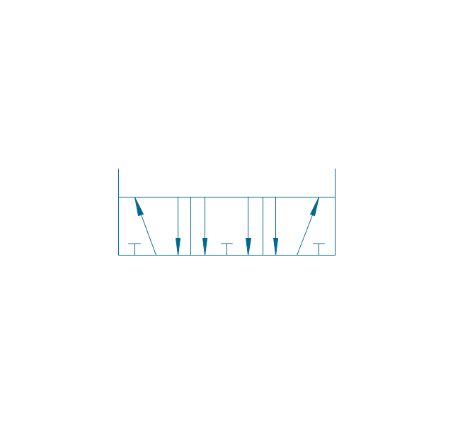
2/2 valve, hydr., finite positions
2/2 valve, hydr., infinite positions

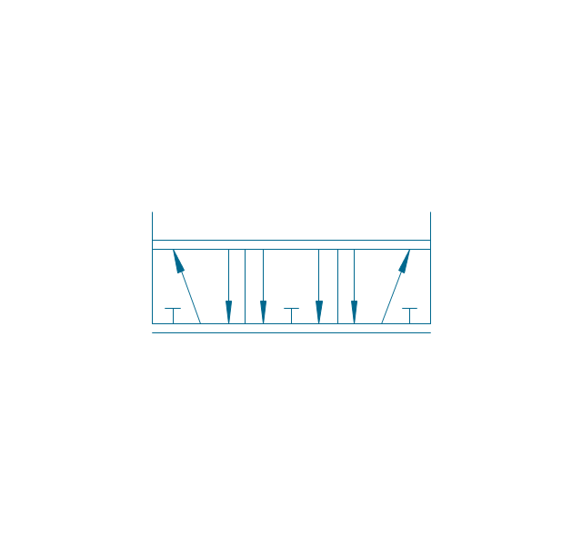
2/2 valve, hydr., ext., fin. pos.
2/2 valve, hydr., ext., infin. pos.
3/2 valve, pneum., finite positions
3/2 valve, pneum., infinite positions
3/2 valve, pneum., ext., fin. pos.
3/2 valve, pneum., ext., infin. pos.
3/2 valve, hydr., finite positions
3/2 valve, hydr., infinite positions
3/2 valve, hydr., ext., fin. pos.
3/2 valve, hydr., ext., infin. pos.
4/2 valve, pneum., finite positions

4/2 valve, pneum., infinite positions
4/2 valve, pneum., ext., fin. pos.
4/2 valve, pneum., ext., infin. pos.
4/2 valve, hydr., finite positions

4/2 valve, hydr., infinite positions

4/2 valve, hydr., ext., fin. pos.
4/2 valve, hydr., ext., infin. pos.
5/2 valve, pneum., finite positions
5/2 valve, pneum., infinite positions
5/2 valve, pneum., ext., fin. pos.

5/2 valve, pneum., ext., infin. pos.

5/2 valve, hydr., finite positions

5/2 valve, hydr., infinite positions
5/2 valve, hydr., ext., fin. pos.
5/2 valve, hydr., ext., infin. pos.
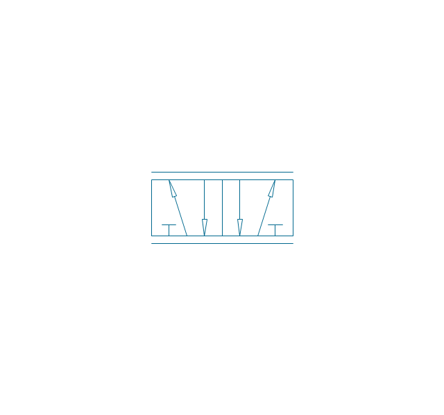
4/3 valve, pneum., finite positions

4/3 valve, pneum., infinite positions
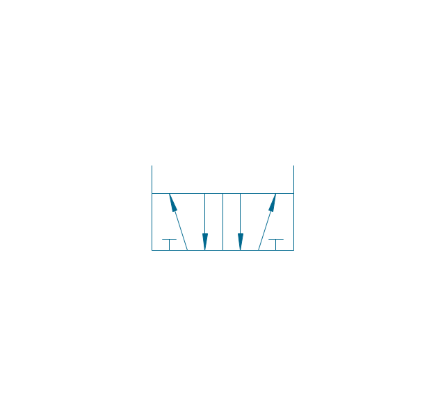
4/3 valve, pneum., ext., fin. pos.
4/3 valve, pneum., ext., infin. pos.
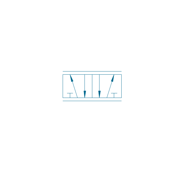
4/3 valve, hydr., finite positions

4/3 valve, hydr., infinite positions

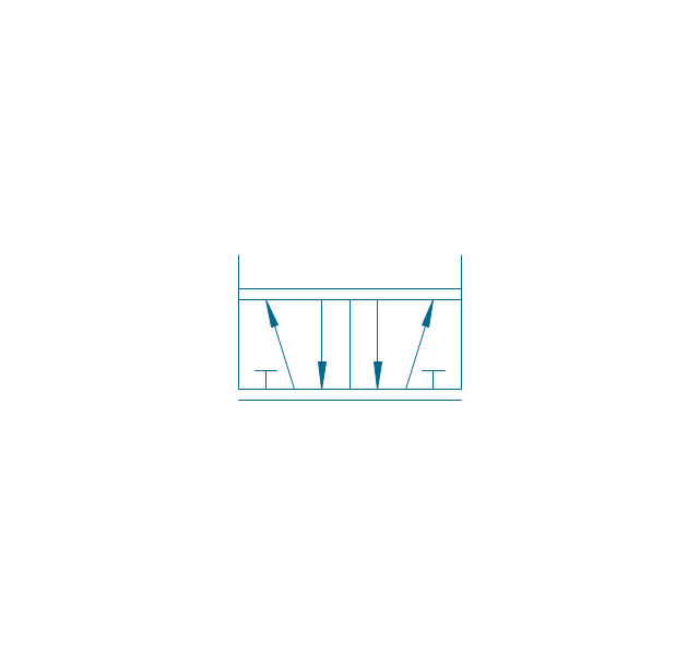
4/3 valve, hydr., ext., fin. pos.

4/3 valve, hydr., ext., infin. pos.
5/3 valve, pneum., finite positions
5/3 valve, pneum., infinite positions
5/3 valve, pneum., ext., fin. pos.
5/3 valve, pneum., ext., infin. pos.
5/3 valve, hydr., finite positions
5/3 valve, hydr., infinite positions
5/3 valve, hydr., ext., fin. pos.
5/3 valve, hydr., ext., infin. pos.
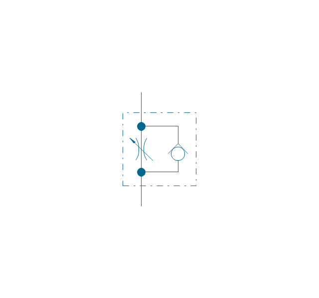
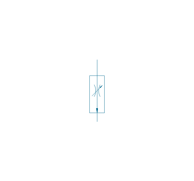
Restrictor valve

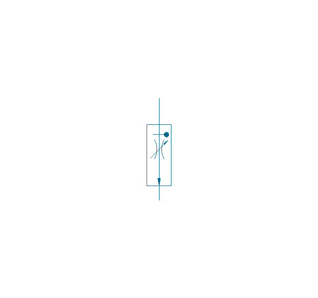
Restrictor valve, adjustable
Gate-valve, norm. open
Gate-valve, norm. open, adj.
Gate-valve, norm. closed

Gate-valve, norm. closed, adj.

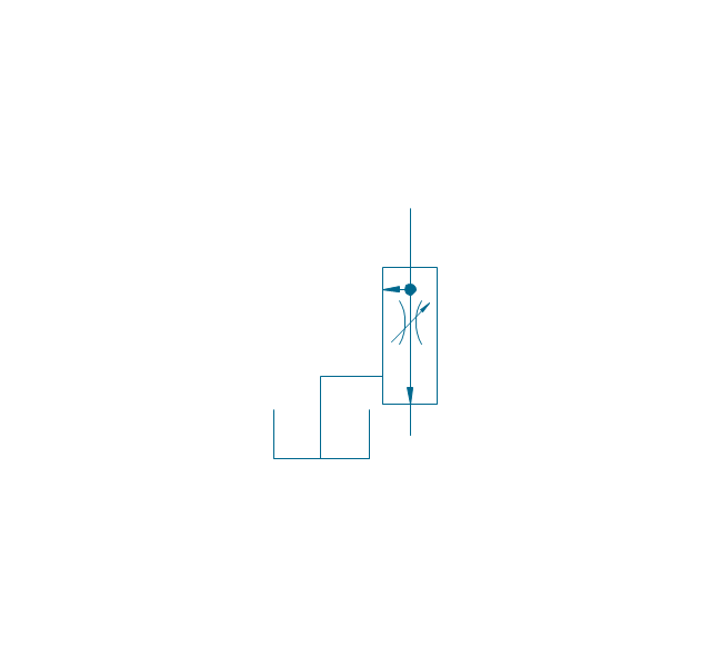
One-way restrictor
One-way restrictor, enclosed
Flow control, series flow
Flow control, temperature compensated
Flow control, bypass flow
Flow divider
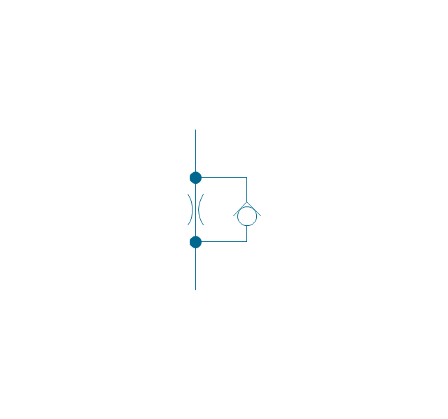
Non-return, pilot controlled
Non-return, pilot contr., spring
Non-return, free
Non-return, spring loaded
Coupling (connect.), 1 valve
,-1-valve-fluid-power-valves---vector-stencils-library.png--diagram-flowchart-example.png)
Coupling (connect.), both valves
,-both-valves-fluid-power-valves---vector-stencils-library.png--diagram-flowchart-example.png)
Coupling (connect.), no valves
,-no-valves-fluid-power-valves---vector-stencils-library.png--diagram-flowchart-example.png)
Coupling (connect.), 1 valve, encl.
,-1-valve,-encl.-fluid-power-valves---vector-stencils-library.png--diagram-flowchart-example.png)
Coupling (connect.), both valves, encl.
,-both-valves,-encl.-fluid-power-valves---vector-stencils-library.png--diagram-flowchart-example.png)
Coupling (connect.), no valves, encl.
,-no-valves,-encl.-fluid-power-valves---vector-stencils-library.png--diagram-flowchart-example.png)
Coupling (discon.), 1 valve
,-1-valve-fluid-power-valves---vector-stencils-library.png--diagram-flowchart-example.png)
Coupling (discon.), both valves
,-both-valves-fluid-power-valves---vector-stencils-library.png--diagram-flowchart-example.png)
Coupling (discon.), no valves
,-no-valves-fluid-power-valves---vector-stencils-library.png--diagram-flowchart-example.png)
Coupling (discon.), 1 valve, encl.
,-1-valve,-encl.-fluid-power-valves---vector-stencils-library.png--diagram-flowchart-example.png)
Coupling (discon.), both valves, encl.
,-both-valves,-encl.-fluid-power-valves---vector-stencils-library.png--diagram-flowchart-example.png)
Coupling (discon.), no valves, encl.
,-no-valves,-encl.-fluid-power-valves---vector-stencils-library.png--diagram-flowchart-example.png)
Shuttle valve
Priority shuttle valve
Quick exhaust
Cartridge valve
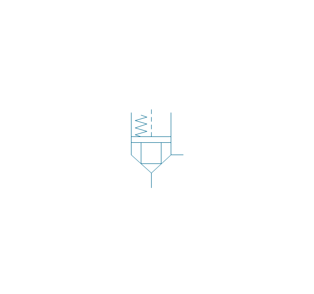
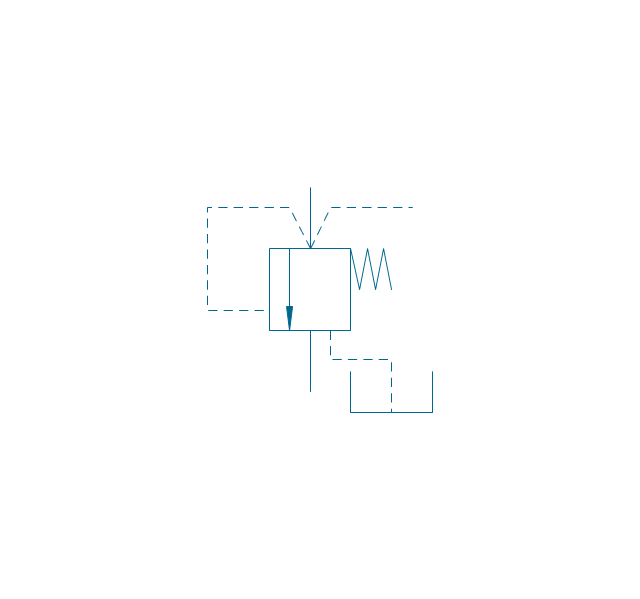
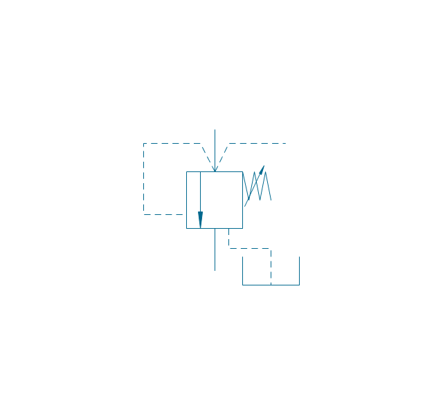
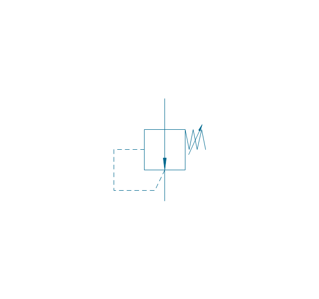
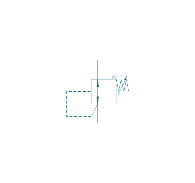
Pressure relief
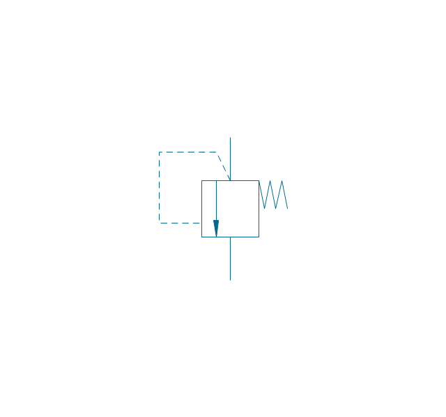
Pressure relief, drain
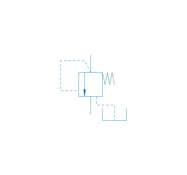
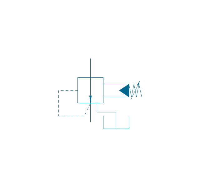
Pressure relief, vent port
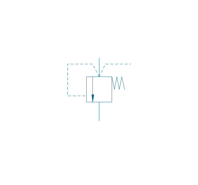
Pressure relief, drain, vent port
Pressure relief, var.
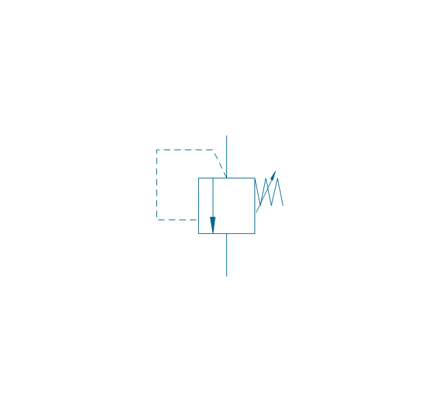
Pressure relief, var., drain
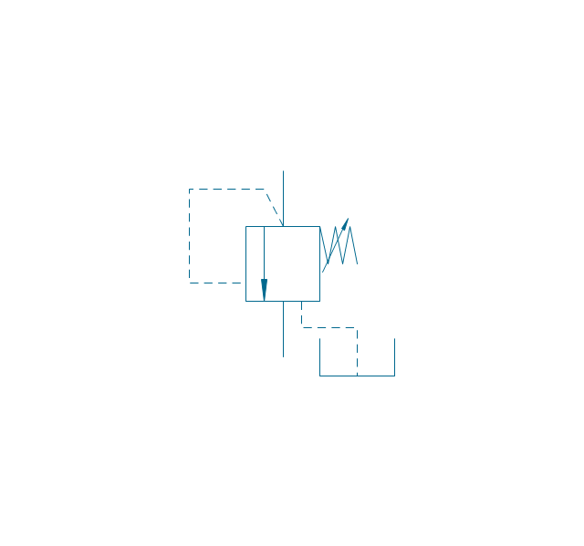
Pressure relief, var., vent port
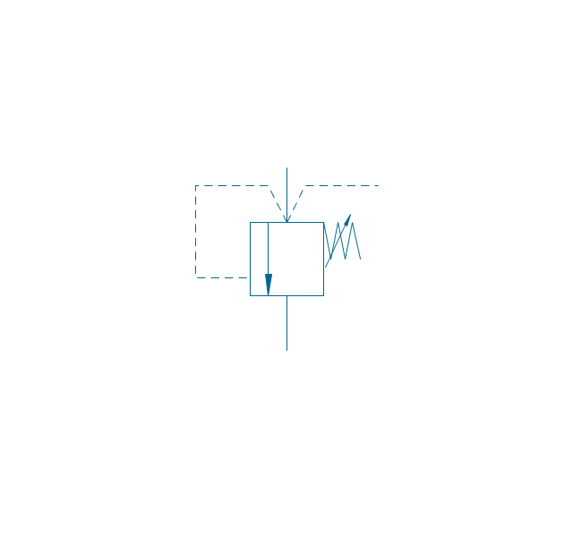
Pressure relief, var., drain, vent port
Pressure relief 2
Pressure reducing, 1 stage
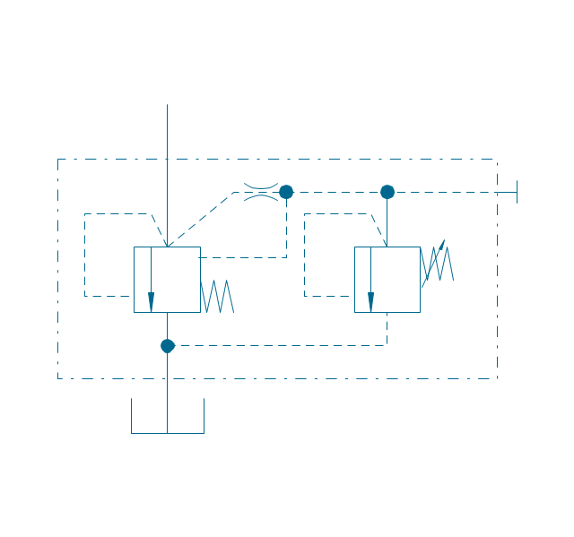
Pressure reducing, 2 stage
Pressure reducing, relief
Pressure relief (E)
-fluid-power-valves---vector-stencils-library.png--diagram-flowchart-example.png)
Classroom Seating Chart Maker

The vector stencil library "HVAC control equipment" contains 81 HVAC control equipment icons.
Use it for drawing HVAC system diagrams, heating, ventilation, air conditioning, refrigeration, automated building control, and environmental control design floor
plans and equipment layouts.
"HVAC (stands for Heating, Ventilation and Air Conditioning) is a control system that applies regulation to a heating and/ or air conditioning system. Usually a sensing device is used to compare the actual state (e.g., temperature) with a target state. Then the control system draws a conclusion what action has to be taken (e.g., start the blower).
More complex HVAC systems can interface to Building Automation System (BAS) to allow the building owners to have more control over the heating or cooling units. The building owner can monitor the system and respond to alarms generated by the system from local or remote locations." [HVAC control system. Wikipedia]
The vector stencils example "Design elements - HVAC control equipment" is included in HVAC Plans solution from the Building Plans area of ConceptDraw Solution
Park.
HVAC control equipment symbols

- Design elements - Valves | Ancient Plumbing Symbols
- Design elements | Plumbing and Piping Plans | Tap Plumbing Symbol
- Design elements - Valves | Check Valve Symbol Flow Direction
- Design elements - Fluid power valves | Valve Symbols
- Design elements - Valves and fittings | Design elements - Valves ...
- Valves and fittings | Design elements - Valves | Flap Valve Symbol
- Valves - Vector stencils library | Design elements - Pipes (part 1 ...
- Design elements - Valves and fittings - Plumbing | Pipe Valve Symbol
- Design elements - HVAC controls | Design elements - Valves ...
- Plumbing and Piping Plans | Mechanical Valve Sysbol Pdf File