 ConceptDraw Solution Park
ConceptDraw Solution Park collects graphic extensions, examples and learning materials
 Fishbone Diagram
Fishbone Diagrams solution extends ConceptDraw DIAGRAM software with templates, samples and library of vector stencils for drawing the Ishikawa diagrams for cause and effect analysis.
 Event-driven Process Chain Diagrams
Event-Driven Process Chain Diagrams solution extends ConceptDraw DIAGRAM functionality with event driven process chain templates, samples of EPC engineering and modeling the business processes, and a vector shape library for drawing the EPC diagrams and EPC flowcharts of any complexity. It is one of EPC IT solutions that assist the marketing experts, business specialists, engineers, educators and researchers in resources planning and improving the business processes using the EPC flowchart or EPC diagram. Use the EPC solutions tools to construct the chain of events and functions, to illustrate the structure of a business process control flow, to describe people and tasks for execution the business processes, to identify the inefficient businesses processes and measures required to make them efficient.
HelpDesk
How to Make Network Diagram

 Computer and Networks Area
The solutions from Computer and Networks Area of ConceptDraw Solution Park collect samples, templates and vector stencils libraries for drawing computer and network diagrams, schemes and technical drawings.
 Workflow Diagrams
Workflow Diagrams solution extends ConceptDraw DIAGRAM software with samples, templates and vector stencils library for drawing the work process flowcharts.
HelpDesk
How to Create a Timeline Diagram

 Entity-Relationship Diagram (ERD)
Entity-Relationship Diagram (ERD) solution extends ConceptDraw DIAGRAM software with templates, samples and libraries of vector stencils from drawing the ER-diagrams by Chen's and crow’s foot notations.
In searching of alternative to MS Visio for MAC and PC with ConceptDraw DIAGRAM

 Value Stream Mapping
Value stream mapping solution extends ConceptDraw DIAGRAM software with templates, samples and vector stencils for drawing the Value Stream Maps (VSM) in lean manufacturing practice.
 Bubble Diagrams
Bubble diagrams have enjoyed great success in software engineering, architecture, economics, medicine, landscape design, scientific and educational process, for ideas organization during brainstorming, for making business illustrations, presentations, planning, design, and strategy development. They are popular because of their simplicity and their powerful visual communication attributes.
 Fishbone Diagrams
The Fishbone Diagrams solution extends ConceptDraw DIAGRAM software with the ability to easily draw the Fishbone Diagrams (Ishikawa Diagrams) to clearly see the cause and effect analysis and also problem solving. The vector graphic diagrams produced using this solution can be used in whitepapers, presentations, datasheets, posters, and published technical material.
HelpDesk
How to Create a Bubble Diagram
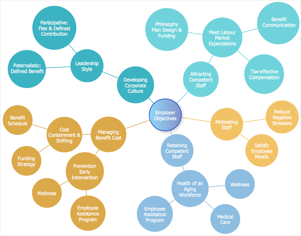
 Circle-Spoke Diagrams
Examples of subject areas that are well suited to this approach are marketing, business, products promotion, process modeling, market, resource, time, and cost analysis. Circle-Spoke Diagrams are successfully used in presentations, conferences, management documents, magazines, reportages, reviews, reports, TV, and social media.
HelpDesk
How to Create an IDEF0 Diagram for an Application Development

 Business Process Diagrams
Business Process Diagrams solution extends the ConceptDraw DIAGRAM BPM software with RapidDraw interface, templates, samples and numerous libraries based on the BPMN 1.2 and BPMN 2.0 standards, which give you the possibility to visualize equally easy simple and complex processes, to design business models, to quickly develop and document in details any business processes on the stages of project’s planning and implementation.
HelpDesk
How to Create an Electrical Diagram

 Venn Diagrams
Venn Diagrams are actively used to illustrate simple set relationships in set theory and probability theory, logic and statistics, mathematics and computer science, linguistics, sociology, and marketing. Venn Diagrams are also often used to visually summarize the status and future viability of a project.
HelpDesk
How to Create a Venn Diagram

- Conceptdraw.com: Mind Map Software, Drawing Tools | Project ...
- Data Flow Diagram Process | DFD - Process of account receivable ...
- Fishbone diagram - Causes of low-quality output
- Data Flow Diagram Process
- DFD - Process of account receivable | Data Flow Diagrams ...
- Decision Making | Block diagram - Customer decision making | Work ...
- Enterprise Architecture Diagrams | Data Flow Diagrams | Fishbone ...
- Entity-relationship diagram (Crow's foot notation)
- UML Diagram for System | Entity-Relationship Diagram (ERD) | Uml ...
- Workflow Diagram Examples | Workflow Diagrams | Flow chart ...
- UML Class Diagram Example - Medical Shop | UML Notation | Basic ...
- Fishbone Diagram | Marketing | Marketing Diagrams | Fishbone ...
- Network topologies diagram | Network Topology | Cisco Network ...
- Circle-Spoke Diagrams
- Tree Diagram App Ipad
- Network Diagram Examples
- Data Flow Diagram Model | DFD - Model of small traditional ...
- Cause and Effect Analysis (Fishbone Diagrams ) | Total Quality ...
- Venn Diagram Examples for Problem Solving. Environmental Social ...
- Network Diagram Examples | Bus network topology diagram | Basic ...