Samples of Flowchart

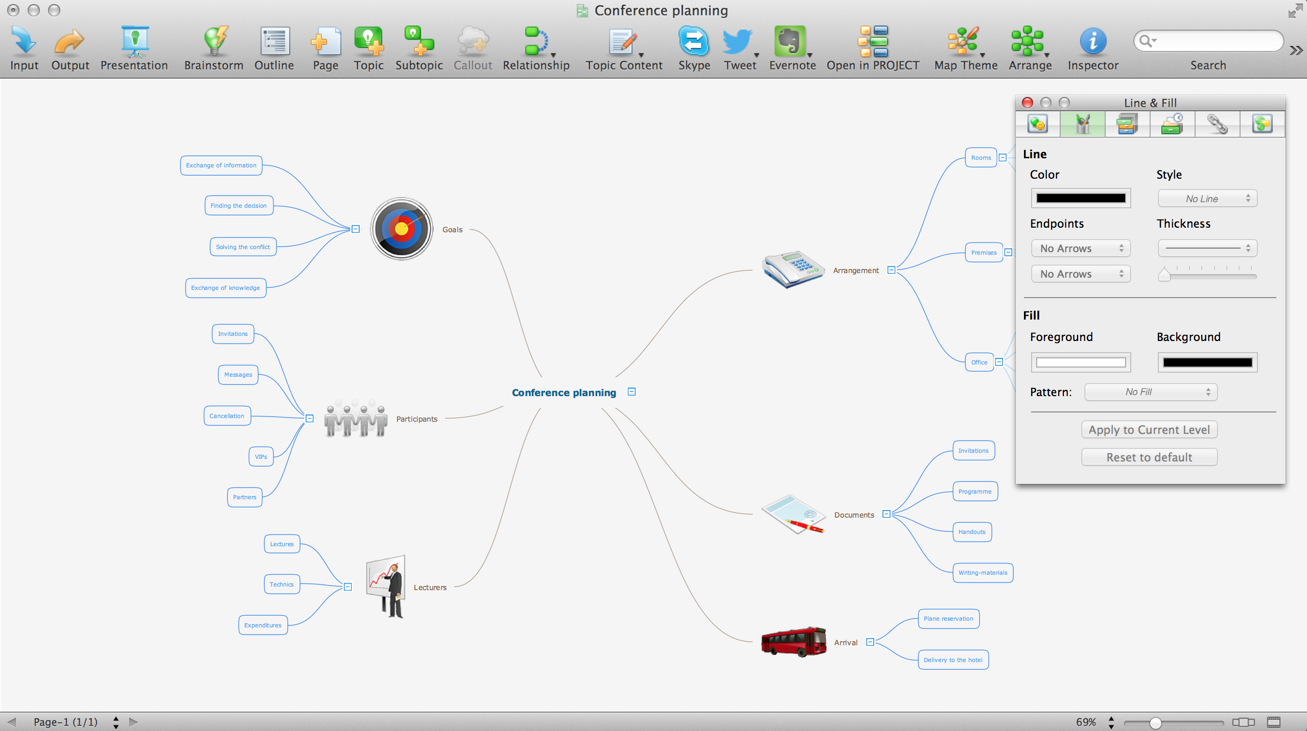
Mind Map Making Software
Electrical Schematic
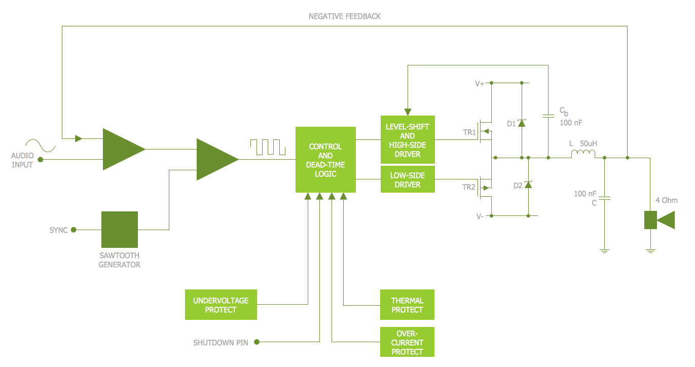
Electrical Diagram

Electrical Schematics

Electrical Symbols, Electrical Diagram Symbols

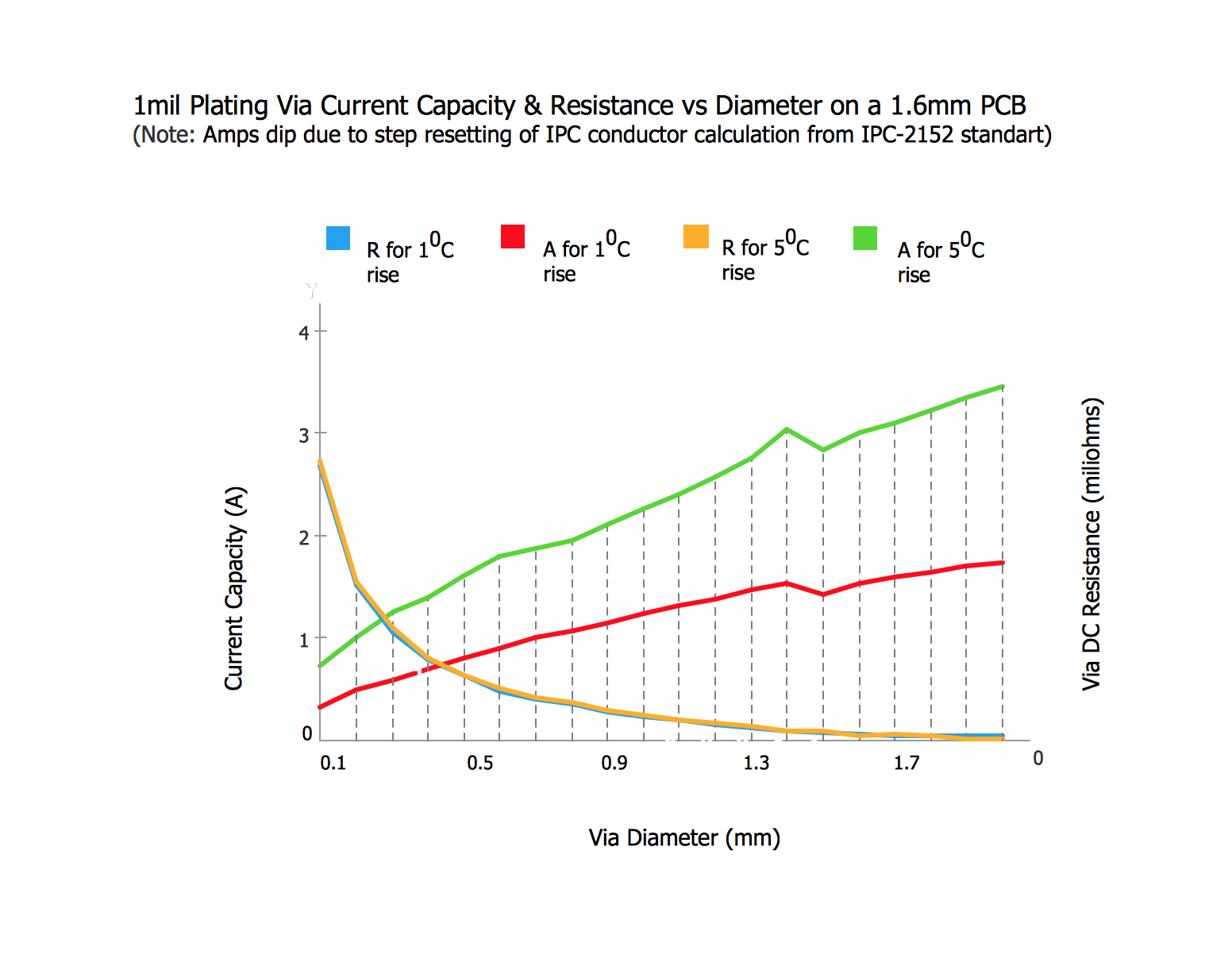
Step Area Graph
Wiring Diagram Floor Software
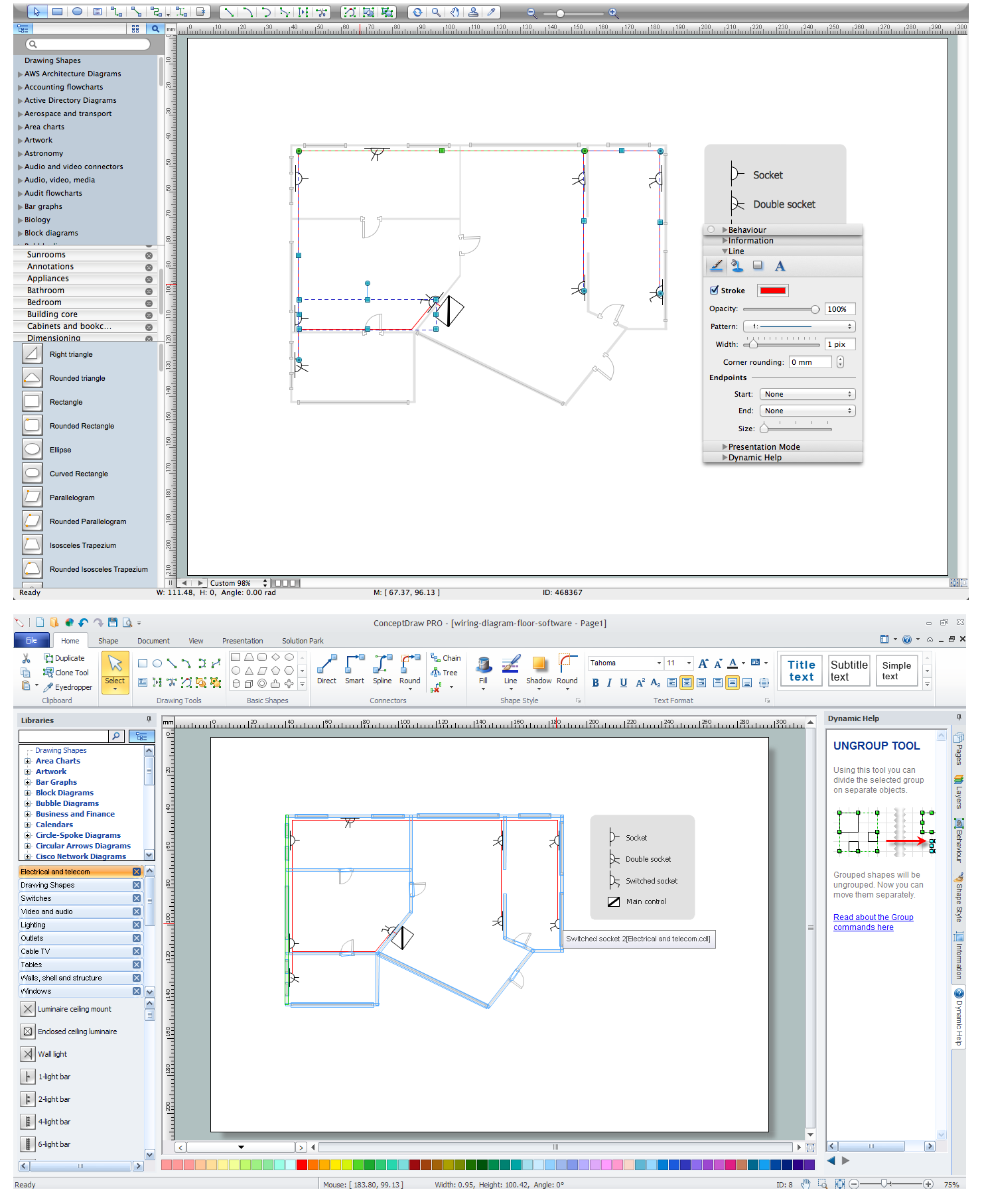
Electrical and Telecom Plan Software

HelpDesk
How to Create an Electrical Diagram

- Ms Project Sample Construction Schedule Pdf
- Ms Project Sample Project Plan Construction Pdf
- How to Convert a Mind Map into MS Project XML | How to Track ...
- Gantt Chart Templates | How to Create Presentation of Your Project ...
- How To use House Electrical Plan Software | Building Drawing ...
- Planned Vs Actual Schedule In Ms Project
- Sample Ms Visio Time Line Drawing
- Factory layout floor plan | Plant Layout Plans | How To use House ...
- Electrical Symbols, Electrical Diagram Symbols | How To use House ...
- Timeline Diagrams | Computer Hardware - Reseller Business Plan ...